- 您現(xiàn)在的位置:買賣IC網(wǎng) > PDF目錄97867 > DS21FF44 (DALLAS SEMICONDUCTOR) DATACOM, FRAMER, PBGA300 PDF資料下載
參數(shù)資料
| 型號: | DS21FF44 |
| 廠商: | DALLAS SEMICONDUCTOR |
| 元件分類: | Digital Transmission Controller |
| 英文描述: | DATACOM, FRAMER, PBGA300 |
| 封裝: | 27 X 27 MM, 1.27 MM PITCH, MCMBGA-300 |
| 文件頁數(shù): | 60/110頁 |
| 文件大小: | 526K |
| 代理商: | DS21FF44 |
第1頁第2頁第3頁第4頁第5頁第6頁第7頁第8頁第9頁第10頁第11頁第12頁第13頁第14頁第15頁第16頁第17頁第18頁第19頁第20頁第21頁第22頁第23頁第24頁第25頁第26頁第27頁第28頁第29頁第30頁第31頁第32頁第33頁第34頁第35頁第36頁第37頁第38頁第39頁第40頁第41頁第42頁第43頁第44頁第45頁第46頁第47頁第48頁第49頁第50頁第51頁第52頁第53頁第54頁第55頁第56頁第57頁第58頁第59頁當(dāng)前第60頁第61頁第62頁第63頁第64頁第65頁第66頁第67頁第68頁第69頁第70頁第71頁第72頁第73頁第74頁第75頁第76頁第77頁第78頁第79頁第80頁第81頁第82頁第83頁第84頁第85頁第86頁第87頁第88頁第89頁第90頁第91頁第92頁第93頁第94頁第95頁第96頁第97頁第98頁第99頁第100頁第101頁第102頁第103頁第104頁第105頁第106頁第107頁第108頁第109頁第110頁
DS21FT44/DS21FF44
53 of 110
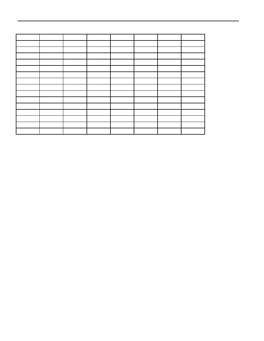
RS1 TO RS16: RECEIVE SIGNALING REGISTERS (Address=30 to 3F Hex)
(MSB)
(LSB)
0
X
Y
X
RS1 (30)
A(1)
B(1)
C(1)
D(1)
A(16)
B(16)
C(16)
D(16)
RS2 (31)
A(2)
B(2)
C(2)
D(2)
A(17)
B(17)
C(17)
D(17)
RS3 (32)
A(3)
B(3)
C(3)
D(3)
A(18)
B(18)
C(18)
D(18)
RS3 (33)
A(4)
B(4)
C(4)
D(4)
A(19)
B(19)
C(19)
D(19)
RS5 (34)
A(5)
B(5)
C(5)
D(5)
A(20)
B(20)
C(20)
D(20)
RS6 (35)
A(6)
B(6)
C(6)
D(6)
A(21)
B(21)
C(21)
D(21)
RS7 (36)
A(7)
B(7)
B(22)
RS8 (37)
A(8)
B(8)
C(8)
D(8)
A(23)
B(23)
C(23)
D(23)
RS9 (38)
A(9)
B(9)
C(9)
D(9)
A(24)
B(24)
C(24)
D(24)
RS10 (39)
A(10)
B(10)
C(10)
D(10)
A(25)
B(25)
C(25)
D(25)
RS11 (3A)
A(11)
B(11)
C(11)
D(11)
A(26)
B(26)
C(26)
D(26)
RS12 (3B)
A(12)
B(12)
C(12)
D(12)
A(27)
B(27)
C(27)
D(27)
RS13 (3C)
A(13)
B(13)
C(13)
D(13)
A(28)
B(28)
C(28)
D(28)
RS14 (3D)
A(14)
B(14)
C(14)
D(14)
A(29)
B(29)
C(29)
D(29)
RS15 (3E)
A(15)
B(15)
C(15)
D(15)
A(30)
B(30)
C(30)
D(30)
RS16 (3F)
SYMBOL
POSITION
NAME AND DESCRIPTION
X
RS1.0/1/3
Spare Bits.
Y
RS1.2
Remote Alarm Bit (integrated and reported in SR1.6).
A(1)
RS2.7
Signaling Bit A for Channel 1
D(30)
RS16.0
Signaling Bit D for Channel 30.
Each Receive Signaling Register (RS1 to RS16) reports the incoming signaling from two timeslots. The
bits in the Receive Signaling Registers are updated on multiframe boundaries so the user can utilize the
Receive Multiframe Interrupt in the Receive Status Register 2 (SR2.7) to know when to retrieve the
signaling bits. The user has a full 2 ms to retrieve the signaling bits before the data is lost. The RS
registers are updated under all conditions.
Their validity should be qualified by checking for
synchronization at the CAS level. In CCS signaling mode, RS1 to RS16 can also be used to extract
signaling information. Via the SR2.7 bit, the user will be informed when the signaling registers have
been loaded with data. The user has 2 ms to retrieve the data before it is lost. The signaling data reported
in RS1 to RS16 is also available at the RSIG and RSER pins.
Three status bits in Status Register 1 (SR1) monitor the contents of registers RS1 through RS16. Status
monitored includes all zeros detection, all ones detection and a change in register contents. The Receive
Signaling All Zeros status bit (SR1.5) is set when over a full multi-frame, RS1 through RS16 contain all
zeros. The Receive Signaling All Ones status bit (SR1.7) is set when over a full multi-frame, RS1
through RS16 contain less than three zeros. A change in the contents of RS1 through RS16 from one
multiframe to the next will cause RSA1 (SR1.7) and RSA0 (SR1.5) status bits to be set at the same time.
The user can enable the INT* pin to toggle low upon detection of a change in signaling by setting either
the IMR1.7 or IMR1.5 bit. Once a signaling change has been detected, the user has at least 1.75 ms to
read the data out of the RS1 to RS16 registers before the data will be lost.
相關(guān)PDF資料 |
PDF描述 |
|---|---|
| DS21FF44N | DATACOM, FRAMER, PBGA300 |
| DS21FT40N | DATACOM, FRAMER, PBGA300 |
| DS21FT40 | DATACOM, FRAMER, PBGA300 |
| DS21FT42 | DATACOM, FRAMER, PBGA300 |
| DS21FT42N | DATACOM, FRAMER, PBGA300 |
相關(guān)代理商/技術(shù)參數(shù) |
參數(shù)描述 |
|---|---|
| DS21FF44N | 功能描述:網(wǎng)絡(luò)控制器與處理器 IC RoHS:否 制造商:Micrel 產(chǎn)品:Controller Area Network (CAN) 收發(fā)器數(shù)量: 數(shù)據(jù)速率: 電源電流(最大值):595 mA 最大工作溫度:+ 85 C 安裝風(fēng)格:SMD/SMT 封裝 / 箱體:PBGA-400 封裝:Tray |
| DS21FT40 | 制造商:DALLAS 制造商全稱:Dallas Semiconductor 功能描述:Four x Three 12 Channel E1 Framer |
| DS21FT40N | 制造商:Rochester Electronics LLC 功能描述: 制造商:Maxim Integrated Products 功能描述: |
| DS21FT42 | 功能描述:網(wǎng)絡(luò)控制器與處理器 IC 4x4 16/4x3 12 Chnl T1/T1 Framer RoHS:否 制造商:Micrel 產(chǎn)品:Controller Area Network (CAN) 收發(fā)器數(shù)量: 數(shù)據(jù)速率: 電源電流(最大值):595 mA 最大工作溫度:+ 85 C 安裝風(fēng)格:SMD/SMT 封裝 / 箱體:PBGA-400 封裝:Tray |
| DS21FT42N | 功能描述:網(wǎng)絡(luò)控制器與處理器 IC 4x4 16/4x3 12 Chnl T1/T1 Framer RoHS:否 制造商:Micrel 產(chǎn)品:Controller Area Network (CAN) 收發(fā)器數(shù)量: 數(shù)據(jù)速率: 電源電流(最大值):595 mA 最大工作溫度:+ 85 C 安裝風(fēng)格:SMD/SMT 封裝 / 箱體:PBGA-400 封裝:Tray |
發(fā)布緊急采購,3分鐘左右您將得到回復(fù)。