- 您現(xiàn)在的位置:買(mǎi)賣(mài)IC網(wǎng) > PDF目錄376982 > DS80C390-QCR Dual CAN High-Speed Microprocessor PDF資料下載
參數(shù)資料
| 型號(hào): | DS80C390-QCR |
| 元件分類(lèi): | 微處理器 |
| 英文描述: | Dual CAN High-Speed Microprocessor |
| 中文描述: | 雙CAN高速微處理器 |
| 文件頁(yè)數(shù): | 24/58頁(yè) |
| 文件大小: | 5486K |
| 代理商: | DS80C390-QCR |
第1頁(yè)第2頁(yè)第3頁(yè)第4頁(yè)第5頁(yè)第6頁(yè)第7頁(yè)第8頁(yè)第9頁(yè)第10頁(yè)第11頁(yè)第12頁(yè)第13頁(yè)第14頁(yè)第15頁(yè)第16頁(yè)第17頁(yè)第18頁(yè)第19頁(yè)第20頁(yè)第21頁(yè)第22頁(yè)第23頁(yè)當(dāng)前第24頁(yè)第25頁(yè)第26頁(yè)第27頁(yè)第28頁(yè)第29頁(yè)第30頁(yè)第31頁(yè)第32頁(yè)第33頁(yè)第34頁(yè)第35頁(yè)第36頁(yè)第37頁(yè)第38頁(yè)第39頁(yè)第40頁(yè)第41頁(yè)第42頁(yè)第43頁(yè)第44頁(yè)第45頁(yè)第46頁(yè)第47頁(yè)第48頁(yè)第49頁(yè)第50頁(yè)第51頁(yè)第52頁(yè)第53頁(yè)第54頁(yè)第55頁(yè)第56頁(yè)第57頁(yè)第58頁(yè)
DS80C390
24 of 58
110199
EXTERNAL RESET PINS
The DS80C390 has both reset input (RST) and reset output (
RSTOL
) pins. The
RSTOL
pin supplies an
active low Reset when the microprocessor is issued a Reset from either a high on the RST pin, a time out
of the watchdog timer, a crystal oscillator fail, or an internally detected power-fail. The timing of the
RSTOL
pin is dependent on the source of the reset.
Reset Type/Source
Power-on reset
External reset
Power fail
Watchdog timer reset
Oscillator fail detect
RSTOL
Duration
65536 t
CLCL
(as described in Power Cycle Timing Characteristics)
< 1.25 machine cycles
65536 t
CLCL
(as described in Power Cycle Timing Characteristics)
2 machine cycles
65536 t
CLCL
(as described in Power Cycle Timing Characteristics)
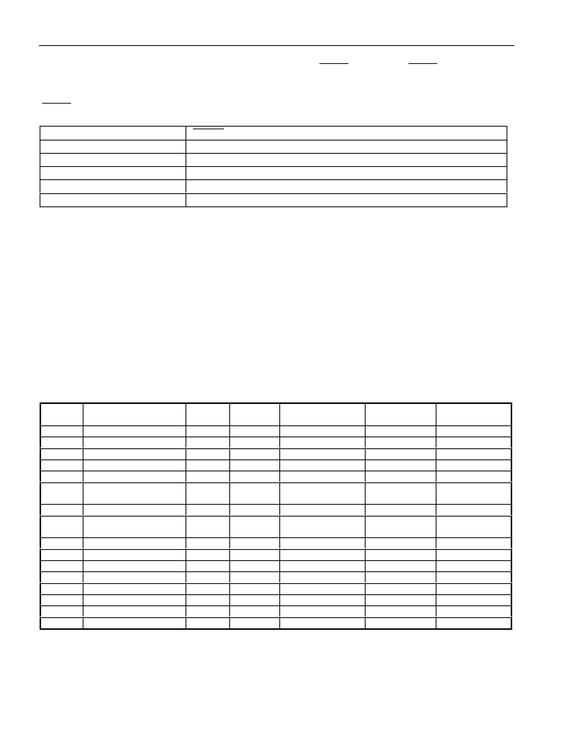
INTERRUPTS
The microcontroller provides 16 interrupt sources with three priority levels. All interrupts, with the
exception of the Power Fail interrupt, are controlled by a series combination of individual enable bits and
a global interrupt enable EA (IE.7). Setting EA to a 1 allows individual interrupts to be enabled.
Clearing EA disables all interrupts regardless of their individual enable settings.
The three available priority levels are low, high, and highest. The highest priority level is reserved for the
Power Fail Interrupt only. All other interrupt priority levels have individual priority bits that when set to
a 1 establish the particular interrupt as high priority. In addition to the user-selectable priorities, each
interrupt also has an inherent natural priority, used to determine the priority of simultaneously occurring
interrupts. The available interrupt sources, their flags, their enables, their natural priority, and their
available priority selection bits are identified in the following table.
INTERRUPT SUMMARY
Table 12
NAME
DESCRIPTION
VECTOR NATURAL
PRIORITY
33h
03h
0Bh
13h
1Bh
23h
FLAG BIT
ENABLE BIT
PRIORITY
CONTROL BIT
N/A
PX0(IP.0)
PT0(IP.1)
PX1(IP.2)
PT1(IP.3)
PS0(IP.4)
PFI
INT0
TF0
INT1
TF1
SCON0
Power Fail Interrupt
External Interrupt 0
Timer 0
External Interrupt 1
Timer 1
TI0 or RI0 from serial
port 0
Timer 2
TI1 or RI1 from serial
port 1
External Interrupt 2
External Interrupt 3
External Interrupt 4
External Interrupt 5
CAN0 Interrupt
CAN1 Interrupt
Watchdog Timer
CAN0/1 Bus Activity
0
1
2
3
4
5
PFI(WDCON.4)
IE0(TCON.1)**
TF0(TCON.5)*
IE1(TCON.3)**
TF1(TCON.7)*
RI_0(SCON0.0)
TI_0(SCON0.1)
TF2(T2CON.7)
RI_1(SCON1.0)
TI_1(SCON1.1)
IE2 (EXIF.4)
IE3 (EXIF.5)
IE4 (EXIF.6)
IE5 (EXIF.7)
various
various
WDIF (WDCON.3)
various
EPFI(WDCON.5)
EX0(IE.0)
ET0(IE.1)
EX1(IE.2)
ET1(IE.3)
ES0(IE.4)
TF2
SCON1
2Bh
3Bh
6
7
ET2(IE.5)
ES1(IE.6)
PT2(IP.7)
PS1(IP.6)
INT2
INT3
INT4
INT5
C0I
C1I
WDTI
CANBUS
Unless marked, all flags must be cleared by the application software.
*
Cleared automatically by hardware when the service routine is entered.
** If edge triggered, flag is cleared automatically by hardware when the service routine is entered. If
level triggered, flag follows the state of the interrupt pin.
43h
4Bh
53h
5Bh
6Bh
73h
63h
7Bh
8
9
10
11
12
13
14
15
EX2 (EIE.0)
EX3 (EIE.1)
EX4 (EIE.2)
EX5 (EIE.3)
C0IE (EIE.6)
C1IE (EIE.5)
EWDI (EIE.4)
CANBIE (EIE.7)
PX2 (EIP.0)
PX3 (EIP.1)
PX4 (EIP.2)
PX5 (EIP.3)
C0IP (EIP.6)
C1IP (EIP.5)
PWDI (EIP.4)
CANBIP (EIP.7)
相關(guān)PDF資料 |
PDF描述 |
|---|---|
| DS80C410 | Network Microcontrollers with Ethernet and CAN |
| DS80C410-FNY | Network Microcontrollers with Ethernet and CAN |
| DS80C411-FNY | Network Microcontrollers with Ethernet and CAN |
| DS8187 | |
| DS850-3 | 850 Watts 12V |
相關(guān)代理商/技術(shù)參數(shù) |
參數(shù)描述 |
|---|---|
| DS80C390-QCR+ | 功能描述:8位微控制器 -MCU Dual CAN High-Speed RoHS:否 制造商:Silicon Labs 核心:8051 處理器系列:C8051F39x 數(shù)據(jù)總線寬度:8 bit 最大時(shí)鐘頻率:50 MHz 程序存儲(chǔ)器大小:16 KB 數(shù)據(jù) RAM 大小:1 KB 片上 ADC:Yes 工作電源電壓:1.8 V to 3.6 V 工作溫度范圍:- 40 C to + 105 C 封裝 / 箱體:QFN-20 安裝風(fēng)格:SMD/SMT |
| DS80C390-QNR | 功能描述:8位微控制器 -MCU Dual CAN High-Speed RoHS:否 制造商:Silicon Labs 核心:8051 處理器系列:C8051F39x 數(shù)據(jù)總線寬度:8 bit 最大時(shí)鐘頻率:50 MHz 程序存儲(chǔ)器大小:16 KB 數(shù)據(jù) RAM 大小:1 KB 片上 ADC:Yes 工作電源電壓:1.8 V to 3.6 V 工作溫度范圍:- 40 C to + 105 C 封裝 / 箱體:QFN-20 安裝風(fēng)格:SMD/SMT |
| DS80C390-QNR+ | 功能描述:8位微控制器 -MCU Dual CAN High-Speed RoHS:否 制造商:Silicon Labs 核心:8051 處理器系列:C8051F39x 數(shù)據(jù)總線寬度:8 bit 最大時(shí)鐘頻率:50 MHz 程序存儲(chǔ)器大小:16 KB 數(shù)據(jù) RAM 大小:1 KB 片上 ADC:Yes 工作電源電壓:1.8 V to 3.6 V 工作溫度范圍:- 40 C to + 105 C 封裝 / 箱體:QFN-20 安裝風(fēng)格:SMD/SMT |
| DS80C400 | 制造商:MAXIM 制造商全稱(chēng):Maxim Integrated Products 功能描述:Network Microcontroller |
| DS80C400_03 | 制造商:MAXIM 制造商全稱(chēng):Maxim Integrated Products 功能描述:Network Microcontroller |
發(fā)布緊急采購(gòu),3分鐘左右您將得到回復(fù)。