- 您現(xiàn)在的位置:買(mǎi)賣(mài)IC網(wǎng) > PDF目錄362688 > EM78P5842 (ELAN Microelctronics Corp .) 8 BIT MICROCONTROLLER PDF資料下載
參數(shù)資料
| 型號(hào): | EM78P5842 |
| 廠商: | ELAN Microelctronics Corp . |
| 元件分類: | 8位微控制器 |
| 英文描述: | 8 BIT MICROCONTROLLER |
| 中文描述: | 8位微控制器 |
| 文件頁(yè)數(shù): | 3/48頁(yè) |
| 文件大小: | 469K |
| 代理商: | EM78P5842 |
第1頁(yè)第2頁(yè)當(dāng)前第3頁(yè)第4頁(yè)第5頁(yè)第6頁(yè)第7頁(yè)第8頁(yè)第9頁(yè)第10頁(yè)第11頁(yè)第12頁(yè)第13頁(yè)第14頁(yè)第15頁(yè)第16頁(yè)第17頁(yè)第18頁(yè)第19頁(yè)第20頁(yè)第21頁(yè)第22頁(yè)第23頁(yè)第24頁(yè)第25頁(yè)第26頁(yè)第27頁(yè)第28頁(yè)第29頁(yè)第30頁(yè)第31頁(yè)第32頁(yè)第33頁(yè)第34頁(yè)第35頁(yè)第36頁(yè)第37頁(yè)第38頁(yè)第39頁(yè)第40頁(yè)第41頁(yè)第42頁(yè)第43頁(yè)第44頁(yè)第45頁(yè)第46頁(yè)第47頁(yè)第48頁(yè)
EM78P5840/5841/5842
8-bit Micro-controller
__________________________________________________________________________________________________________________________________________________________________
* This specification is subject to change without notice.
2004/11/10 V2.6
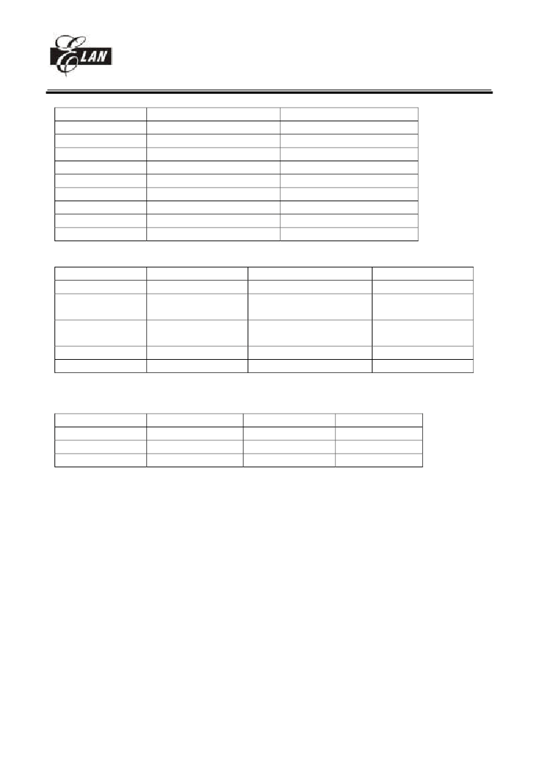
Table2: the major differences between EM78P5830 and EM78P5840 series:
EM78P5830 series
CID RAM
ERIC mode
IRC mode
WDT source
Crystal or PLL
External CNT1 input
P71 pull high
Internal pull high
/RESET pin
PLLC pin
XIN, XOUT
Table3: the major differences between ICE5840, EM78P5840 and EM785840:
ICE5840
CID RAM
1024 byte
CID RAM address auto
+1
EM78P5840 series
NA
Under 6M Hz
2M / 4M Hz
IRC1
Shared with P94
External pull high
Shared with P71
Shared with P70 and ERCI
Shared with P60 and P61
256 byte
NA
NA
NA
/RESET only
PLLC only
Crystal input
EM78P5840 series
NA
EM785840 series
NA
V
NA
NA
CNT1 (**)
8 bit counter
8 bit counter
8 or 16 (shared with
CNT2) bit counter
V
8
CNT2 (**)
STACK
V
12
X
8
** CNT2 is only exist on EM78P5840/41/42 and EM785840/41/42, CNT2 is un-support on ICE5840.
Table4: Differences between EM78P5840, EM78P5841 and EM78P5842:
EM78P5840
Pin count
18
PWM
X
IO (MAX)
16
User Application Note
(Before using this chip, take a look at the following description note, it includes important messages.)
1. There are some undefined bits in the registers. The values in these bits are unpredicted. These
bits are not allowed to use. We use the symbol “-” in the spec to recognize them.
A fixed value
must be write in some specific unused bits by software or some unpredicted wrong will occur.
2. You will see some names for the register bits definitions. Some name will be appear very
frequently in the whole spec. The following describes the meaning for the register’s definitions
such as bit type, bit name, bit number and so on.
EM78P5841
20
2 channel
18
EM78P5842
24
2 channel
22
相關(guān)PDF資料 |
PDF描述 |
|---|---|
| EM78P809N | 8-BIT MICROCONTROLLER |
| EM78P809NM | 8-BIT MICROCONTROLLER |
| EM78P809NP | 8-BIT MICROCONTROLLER |
| EM78P809NS | 8-BIT MICROCONTROLLER |
| EM78P860 | 8 -BIT MICRO-CONTROLLER |
相關(guān)代理商/技術(shù)參數(shù) |
參數(shù)描述 |
|---|---|
| EM7A8620 | 制造商:EMC 制造商全稱:ELAN Microelectronics Corp 功能描述:Voice over IP |
| EM7G | 制造商:GULFSEMI 制造商全稱:Gulf Semiconductor 功能描述:ULTRAFAST EFFICIENT PLASTIC SILICON RECTIFIER VOLTAGE: 1000V CURRENT: 1.0A |
| EM800 | 制造商:EDI 制造商全稱:Electronic devices inc. 功能描述:HIGH VOLTAGE HIGH CURRENT MINIATURE RECTIFIERS |
| EM8000EHP | 制造商:JDSU 制造商全稱:JDS Uniphase Corporation 功能描述:The industrya??s most compact 100 G test solution |
| EM800-DCM | 制造商:MRV 制造商全稱:MRV 功能描述:LambdaDriver Dispersion Compensation Module (EM800/1600-DCM and DCMD) |
發(fā)布緊急采購(gòu),3分鐘左右您將得到回復(fù)。