- 您現(xiàn)在的位置:買賣IC網(wǎng) > PDF目錄68995 > FMS2704T1C (FAIRCHILD SEMICONDUCTOR CORP) SPECIALTY ANALOG CIRCUIT, PDSO24 PDF資料下載
參數(shù)資料
| 型號: | FMS2704T1C |
| 廠商: | FAIRCHILD SEMICONDUCTOR CORP |
| 元件分類: | 模擬信號調(diào)理 |
| 英文描述: | SPECIALTY ANALOG CIRCUIT, PDSO24 |
| 封裝: | TSSOP-24 |
| 文件頁數(shù): | 23/39頁 |
| 文件大?。?/td> | 173K |
| 代理商: | FMS2704T1C |
第1頁第2頁第3頁第4頁第5頁第6頁第7頁第8頁第9頁第10頁第11頁第12頁第13頁第14頁第15頁第16頁第17頁第18頁第19頁第20頁第21頁第22頁當(dāng)前第23頁第24頁第25頁第26頁第27頁第28頁第29頁第30頁第31頁第32頁第33頁第34頁第35頁第36頁第37頁第38頁第39頁

FMS2704/FMS2704L
PRODUCT SPECIFICATION
REV. 1.01 12/2/99
3
Nominal thermal diode sensitivity is 199.7V/°C. Diode volt-
age variation over a –40 to +125°C temperature range, is
approximately 300 to 800mV, while the difference voltage
variation is approximately 50 to 110mV. Overall sensitivity of
the conversion is 1°C/lsb.
Voltmeters
If the TACA3/V5, TACB3/V6 or the DX2-1/V4-1 inputs are
congured to measure voltage, corresponding tachometer or
diode registers are disabled. V6-1 inputs are sequentially sam-
pled by an Analog Multiplexer, prior to digitization by the A/D
Converter with 8-bit accuracy over a 0–1300mV range. Using
external voltage dividers, each incoming voltage should be
normalized to 1000mV.
Upper and Lower Voltage Thresholds are common to all six
voltmeters. If an input violates a threshold, a ag is set in the
Voltmeter Conguration Register. A voltage error will cause a
maskable interrupt.
Fan Speed Controller
If the FMS2704 is operating in the controller mode, local and/
or remote temperatures: TL, TR1 and TR2 establish the fan
speed drive voltages or PWM output. Fan drive voltage range
is 0–2.5V corresponding to 0–255 DAC value.
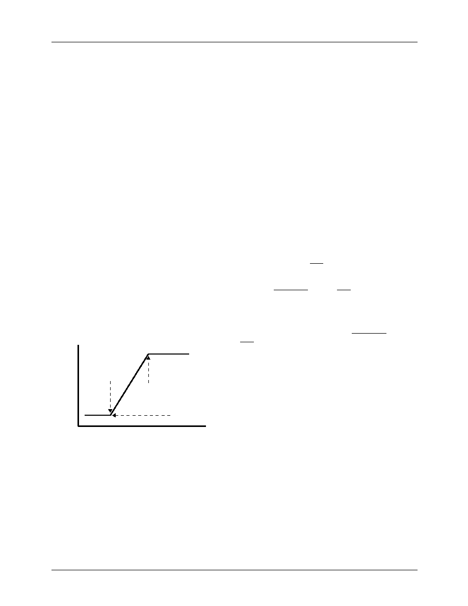
Overall response to one sensor will be a straight-line segment
that is dened by the upper and lower temperatures and the
minimum fan speed. Maximum fan speed always corresponds
to SPEED7-0 = 255.
For each temperature input, a fan speed value is calculated as a
function of temperature along a straight line segment preset to
match the thermal characteristics of the system environment.
The value inserted into the fan speed register is the sum of the
responses of the local and two remote diode segments. Updat-
ing control points through the Serial Bus can change response.
Remote and Local responses can be set up with different:
1.
Idle temperatures.
2.
Full speed temperatures.
3.
Idle speed values
By varying the balance between these parameters, over limited
ranges, either local or remote temperatures can dominate the
fan speed. With both remote temperature inputs processed
against the same values, fan speed control parameters are
established through three groups of six registers. There is one
group for each temperature input, while within each group
there are four registers containing the following data:
1.
FANLO7-0, the idle-speed fan-drive value if the
temperature is below TEMPLO7-0.
2.
TEMPLO7-0, the threshold for the start of fan drive rising
from RFANLO7-0 in proportion to temperature minus
TEMPLO7-0.
3.
TEMPHI7-0, the limit above which the fan drive will
have the value 255.
4.
SLOPE7-0 the incremental rate of fan speed versus
temperature.
Either the analog output from the D/A or the PWM digital out-
put can be selected.
Reset Generators
If VCC
≤ 2.9/4.4V, then RST = L and internal reset is active,
resetting all internal registers to default values.
If the input STANDBY = L, then RST = L and the Standby
Mode is active with sensing suspended and tachometer,
temperatures and voltage register values frozen, while supply
current is minimized. Internal reset in not active.
After input VCC > 2.9/4.4V and input, STANDBY = H, then
RST = L for a timeout period of 0.2 seconds.
Serial Interface
Registers are accessed through an I2C/SMBus compatible
Serial Interface located at the address selected by the A
address pin.
Registers
Registers setup the monitoring conguration and report status:
Conguration: Establish the mode of operation: Run/
standby, Interrupt control, etc.
Status: Report violations of limits or trip points and fault
conditions.
Tachometer: Fan speed periods.
Temperature: Local and remote temperatures in °C.
Voltage: Digitized voltage inputs.
Limits: Tachometer, Temperature and Voltage limit and trip
point values.
Fan Speed Controller: minimum fan speed, lowest tempera-
ture, slope.
F
a
n
S
p
e
d
D
ri
v
e
V
a
lu
e
Temperature
Full Speed Value = 255
Full Speed
Temperature
Idle Speed
Temperature
Idle Speed
Value
相關(guān)PDF資料 |
PDF描述 |
|---|---|
| FMS6501MSA28X_NL | 12-CHANNEL, AUDIO/VIDEO SWITCH, PDSO28 |
| FN3000-810-830 | PLL FREQUENCY SYNTHESIZER, DMA37 |
| FNA41060 | AC MOTOR CONTROLLER, DMA26 |
| FNB41560 | AC MOTOR CONTROLLER, DMA26 |
| FNW500R4 | 1-OUTPUT 504 W DC-DC REG PWR SUPPLY MODULE |
相關(guān)代理商/技術(shù)參數(shù) |
參數(shù)描述 |
|---|---|
| FMS2A | 制造商:ROHM Semiconductor 功能描述:100 mA, 40 V, 2 CHANNEL, PNP, Si, SMALL SIGNAL TRANSISTOR |
| FMS2T148 | 制造商:ROHM Semiconductor 功能描述: |
| FMS3 | 制造商:MITA 功能描述:12M COIL SA 38X16MM TRUNK |
| FMS300 | 制造商:Black Box Corporation 功能描述:CAT6 SHIELDED JACK 90 DEGREE |
| FMS3110 | 制造商:FAIRCHILD 制造商全稱:Fairchild Semiconductor 功能描述:Triple Video D/A Converters 3 x 10 bit, 150 Ms/s |
發(fā)布緊急采購,3分鐘左右您將得到回復(fù)。