- 您現(xiàn)在的位置:買賣IC網(wǎng) > PDF目錄382968 > FS612509-01 (Electronic Theatre Controls, Inc.) 1:9 ZERO DELAY CLOCK BUFFER IC PDF資料下載
參數(shù)資料
| 型號: | FS612509-01 |
| 廠商: | Electronic Theatre Controls, Inc. |
| 英文描述: | 1:9 ZERO DELAY CLOCK BUFFER IC |
| 中文描述: | 1:9零延遲時鐘緩沖器集成電路 |
| 文件頁數(shù): | 4/8頁 |
| 文件大?。?/td> | 81K |
| 代理商: | FS612509-01 |

AMERICAN MICROSYSTEMS, INC.
November 2000
ISO9001
QS9000
4
FS612509-01/-02
1:9 Zero-Delay Clock Buffer IC
5.0 Electrical Specifications
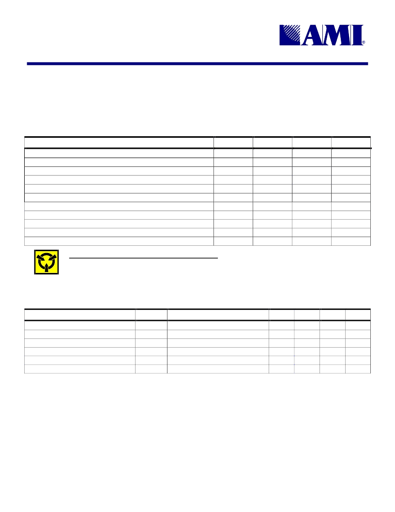
Table 3: Absolute Maximum Ratings
Stresses above those listed under Absolute Maximum Ratings may cause permanent damage to the device. These conditions represent a stress rating only, and functional operation of the device at
these or any other conditions above the operational limits noted in this specification is not implied. Exposure to maximum rating conditions for extended conditions may affect device performance,
functionality, and reliability.
PARAMETER
SYMBOL
MIN.
MAX.
UNITS
Supply Voltage, dc, Clock Buffers (V
SS
= ground)
Supply Voltage, dc, Core
AV
DD
V
DD
V
I
V
O
I
IK
I
OK
T
S
T
A
T
J
V
SS
- 0.5
V
SS
- 0.5
V
SS
- 0.5
V
SS
- 0.5
-50
7
V
7
V
Input Voltage, dc
V
DD
+ 0.5
V
DD
+ 0.5
50
V
Output Voltage, dc
V
Input Clamp Current, dc (V
I
< 0 or V
I
> V
DD
)
Output Clamp Current, dc (V
I
< 0 or V
I
> V
DD
)
Storage Temperature Range (non-condensing)
mA
-50
50
mA
-65
150
°C
Ambient Temperature Range, Under Bias
Junction Temperature
Lead Temperature (soldering, 10s)
Static Discharge Voltage Protection (MIL-STD 883E, Method 3015.7)
-55
125
125
260
2
°C
°C
°C
kV
CAUTION: ELECTROSTATIC SENSITIVE DEVICE
Permanent damage resulting in a loss of functionality or performance may occur if this device is subjected to a high-energy
electrostatic discharge.
Table 4: Operating Conditions
PARAMETER
SYMBOL
CONDITIONS/DESCRIPTION
MIN.
TYP.
MAX.
UNITS
Supply Voltage, Core and Outputs
Ambient Operating Temperature Range
Output Load Capacitance
Input Frequency
Input Duty Cycle
Input Rise/Fall Time
V
DD
T
A
C
L
f
CLK
3.3V ± 10%
3.0
0
3.3
3.6
70
15
140
60
3
V
°C
pF
MHz
%
ns
CLK
CLK
CLK
50
40
相關(guān)PDF資料 |
PDF描述 |
|---|---|
| FS612509-02 | 1:9 ZERO DELAY CLOCK BUFFER IC |
| FS6127 | VCXO CLOCK GENERATOR IC |
| FS6127-01 | VCXO CLOCK GENERATOR IC |
| FS6128-01 | PLL Clock Generator IC with VCXO |
| FS6128-04 | PLL CLOCK GENERATOR IC WITH VCXO |
相關(guān)代理商/技術(shù)參數(shù) |
參數(shù)描述 |
|---|---|
| FS612509-02 | 制造商:未知廠家 制造商全稱:未知廠家 功能描述:1:9 ZERO DELAY CLOCK BUFFER IC |
| FS6127 | 制造商:未知廠家 制造商全稱:未知廠家 功能描述:VCXO CLOCK GENERATOR IC |
| FS6127-01 | 制造商:未知廠家 制造商全稱:未知廠家 功能描述:VCXO CLOCK GENERATOR IC |
| FS6128-01 | 制造商:未知廠家 制造商全稱:未知廠家 功能描述:PLL Clock Generator IC with VCXO |
| FS6128-04 | 制造商:未知廠家 制造商全稱:未知廠家 功能描述:PLL CLOCK GENERATOR IC WITH VCXO |
發(fā)布緊急采購,3分鐘左右您將得到回復(fù)。