- 您現(xiàn)在的位置:買賣IC網(wǎng) > PDF目錄67593 > FW330F1-33T 1-OUTPUT 330 W DC-DC REG PWR SUPPLY MODULE PDF資料下載
參數(shù)資料
| 型號: | FW330F1-33T |
| 元件分類: | 電源模塊 |
| 英文描述: | 1-OUTPUT 330 W DC-DC REG PWR SUPPLY MODULE |
| 封裝: | 2.40 X 4.60 INCH, 0.57 INCH HEIGHT, POWER MODULE |
| 文件頁數(shù): | 4/29頁 |
| 文件大小: | 347K |
| 代理商: | FW330F1-33T |
第1頁第2頁第3頁當前第4頁第5頁第6頁第7頁第8頁第9頁第10頁第11頁第12頁第13頁第14頁第15頁第16頁第17頁第18頁第19頁第20頁第21頁第22頁第23頁第24頁第25頁第26頁第27頁第28頁第29頁
Tyco Electronics Corp.
11
Advance Data Sheet
March 2000
36 to 75 Vdc Input, 3.6, 3.3, 2.5, 2.0, or 1.8 Vdc Output; 180 W to 330 W
FW330 Power Modules: dc-dc Converters;
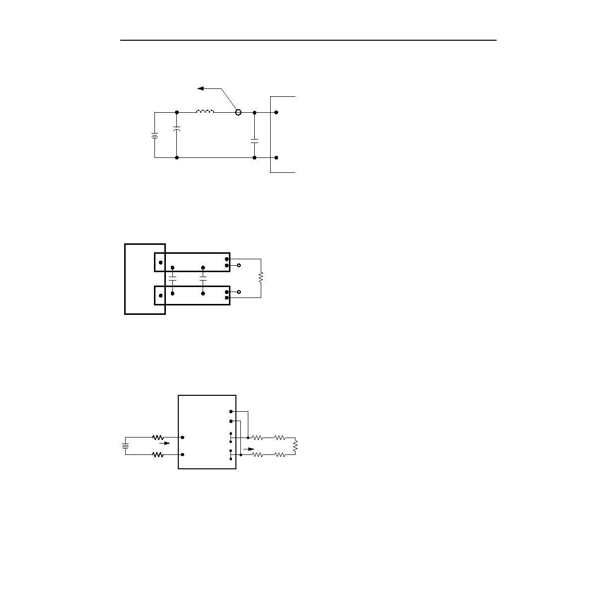
Test Congurations
8-203 (C).o
Note: Measure input reected-ripple current with a simulated source
inductance (LTEST) of 12 H. Capacitor CS offsets possible bat-
tery impedance. Measure current as shown above.
Figure 17. Input Reected-Ripple Test Setup
8-513 (C).q
Note: Use a load capacitance as indicated in the Output Specica-
tions table. Scope measurement should be made using a BNC
socket. Position the load between 50 mm and 76 mm (2 in. and
3 in.) from the module.
Figure 18. Peak-to-Peak Output Noise
Measurement Test Setup
8-683 (C).f
Note: All measurements are taken at the module terminals. When
socketing, place Kelvin connections at module terminals to
avoid measurement errors due to socket contact resistance.
Figure 19. Output Voltage and Efciency
Measurement Test Setup
Design Considerations
Input Source Impedance
The power module should be connected to a low
ac-impedance input source. Highly inductive source
impedances can affect the stability of the power mod-
ule. For the test conguration in Figure 17, a 100 F
electrolytic capacitor (ESR < 0.3
at 100 kHz)
mounted close to the power module helps ensure sta-
bility of the unit. For other highly inductive source
impedances, consult the factory for further application
guidelines.
Safety Considerations
For safety-agency approval of the system in which the
power module is used, the power module must be
installed in compliance with the spacing and separation
requirements of the end-use safety agency standard,
i.e.,
UL1950, CSA C22.2 No. 950-95, and VDE 0805
(EN60950, IEC950).
If the input source is non-SELV (ELV or a hazardous
voltage greater than 60 Vdc and less than or equal to
75 Vdc), for the module’s output to be considered meet-
ing the requirements of safety extra-low voltage
(SELV), all of the following must be true:
s
The input source is to be provided with reinforced
insulation from any hazardous voltages, including the
ac mains.
s
One VI pin and one VO pin are to be grounded, or
both the input and output pins are to be kept oating.
s
The input pins of the module are not operator acces-
sible.
s
Another SELV reliability test is conducted on the
whole system, as required by the safety agencies, on
the combination of supply source and the subject
module to verify that under a single fault, hazardous
voltages do not appear at the module’s output.
Note: Do not ground either of the input pins of the
module without grounding one of the output pins.
This may allow a non-SELV voltage to appear
between the output pin and ground.
The power module has extra-low voltage (ELV) outputs
when all inputs are ELV.
The input to these units is to be provided with a maxi-
mum 20 A normal-blow fuse in the ungrounded lead.
TO OSCILLOSCOPE
12 H
VI(+)
VI(–)
BATTERY
LTEST
Cs 220 F
ESR < 0.1
@ 20
°C, 100kHz
100 F
ESR < 0.3
@ 100 kHz
VO(+)
VO(–)
RESISTIVE
LOAD
SCOPE
COPPER STRIP
VI(–)
VO(+)
SENSE(+)
SENSE(–)
VO(–)
VI(+)
IO
LOAD
CONTACT AND
DISTRIBUTION LOSSES
SUPPLY
II
CONTACT
RESISTANCE
η
VO +
() – VO –
()
[]IO
VI +
() – VI –
()
[]II
--------------------------------------------------
x 100 %
=
相關PDF資料 |
PDF描述 |
|---|---|
| FW330Y1-33T | 1-OUTPUT 180 W DC-DC REG PWR SUPPLY MODULE |
| FW400R61-18 | 1-OUTPUT 392 W DC-DC REG PWR SUPPLY MODULE |
| FX2030C | SPECIALTY CONSUMER CIRCUIT, DIP42 |
| FX2030Z | SPECIALTY CONSUMER CIRCUIT, DIP42 |
| FX980L6 | SPECIALTY CONSUMER CIRCUIT, PQCC44 |
相關代理商/技術參數(shù) |
參數(shù)描述 |
|---|---|
| FW330F1-59T | 制造商:GE Energy (formerly Lineage Power) 功能描述:108755794 |
| FW330G71-56T | 制造商:GE Energy (formerly Lineage Power) 功能描述:Module DC-DC 1-OUT 2.5V 100A 330W 22-Pin |
| FW332 | 制造商:未知廠家 制造商全稱:未知廠家 功能描述: |
| FW340 | 制造商:SANYO 制造商全稱:Sanyo Semicon Device 功能描述:N-Channel and P-Channel Silicon MOSFETs General-Purpose Switching Device |
| FW-34-01-F-D-250-100 | 制造商:Samtec Inc 功能描述:.050'' BOARD SPACERS - Bulk |
發(fā)布緊急采購,3分鐘左右您將得到回復。