- 您現(xiàn)在的位置:買賣IC網(wǎng) > PDF目錄1922 > HA456CM (Intersil)IC VIDEO CROSSPOINT SWIT 44PLCC PDF資料下載
參數(shù)資料
| 型號(hào): | HA456CM |
| 廠商: | Intersil |
| 文件頁(yè)數(shù): | 8/13頁(yè) |
| 文件大?。?/td> | 0K |
| 描述: | IC VIDEO CROSSPOINT SWIT 44PLCC |
| 標(biāo)準(zhǔn)包裝: | 26 |
| 功能: | 視頻交叉點(diǎn)開關(guān) |
| 電路: | 1 x 8:8 |
| 電壓電源: | 雙電源 |
| 電壓 - 電源,單路/雙路(±): | ±4.5 V ~ 5.5 V |
| 電流 - 電源: | 68mA |
| 工作溫度: | 0°C ~ 70°C |
| 安裝類型: | 表面貼裝 |
| 封裝/外殼: | 44-LCC(J 形引線) |
| 供應(yīng)商設(shè)備封裝: | 44-PLCC |
| 包裝: | 管件 |
第1頁(yè)第2頁(yè)第3頁(yè)第4頁(yè)第5頁(yè)第6頁(yè)第7頁(yè)當(dāng)前第8頁(yè)第9頁(yè)第10頁(yè)第11頁(yè)第12頁(yè)第13頁(yè)

4
FN4153.7
September 26, 2008
Absolute Maximum Ratings
Thermal Information
Supply Voltage (V+ to V-). . . . . . . . . . . . . . . . . . . . . . . . . . . . . . 12V
Positive Supply Voltage (V+) Referred to AGND . . . . . . . . . . . . . 6V
Negative Supply Voltage (V-) Referred to AGND. . . . . . . . . . . . -6V
DGND Voltage . . . . . . . . . . . . . . . . . . . . . . . . . . . . . . . . AGND ±1V
Analog Input Voltage . . . . . . . . . . . . . . . . . . . . . . . . . . . . ±
VSUPPLY
Digital Input Voltage . . . . . . . . . . . . . . (V+ + 0.3V) to (DGND - 0.3V)
ESD Rating
Human Body Model (Per MIL-STD-883 Method 3015.7) . . . . 1.5kV
Operating Conditions
Temperature Range . . . . . . . . . . . . . . . . . . . . . . . . . . . 0°C to +70°C
Supply Voltage Range (Typical). . . . . . . . . . . . . . . . ±
4.5V to ±5.5V
Thermal Resistance (Typical, Note 1)
θJA (°C/W)
PLCC Package. . . . . . . . . . . . . . . . . . . . . . . . . . . . .
47
Maximum Junction Temperature . . . . . . . . . . . . . . . . . . . . . +150°C
Maximum Storage Temperature Range . . . . . . . . . -65°C to +150°C
Pb-free reflow profile . . . . . . . . . . . . . . . . . . . . . . . . . .see link below
CAUTION: Do not operate at or near the maximum ratings listed for extended periods of time. Exposure to such conditions may adversely impact product reliability and
result in failures not covered by warranty.
NOTE:
1.
θJA is measured with the component mounted on a low effective thermal conductivity test board in free air. See Tech Brief TB379 for details.
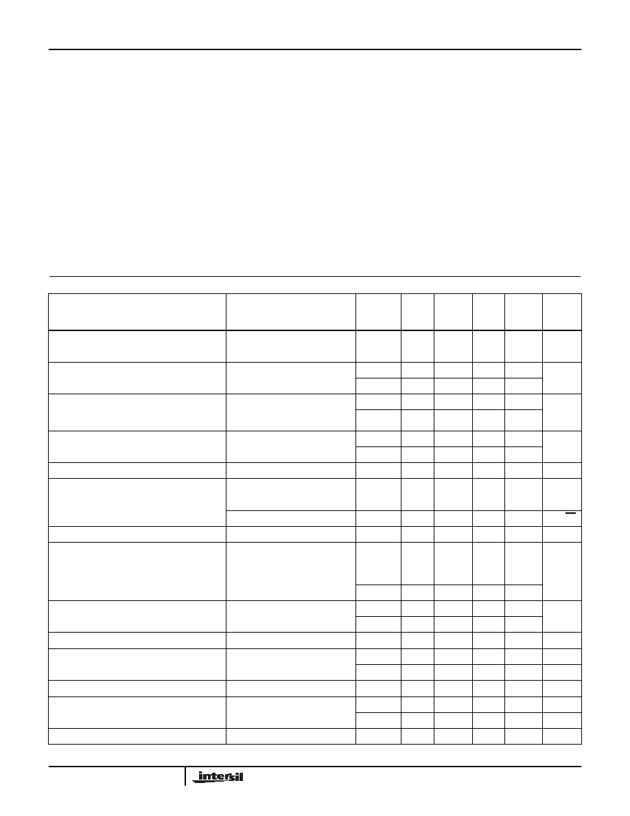
Electrical Specifications
PARAMETER
TEST CONDITIONS
TEST
LEVEL
(Note 3)
TEMP
(°C)
MIN
(Note 7)
TYP
MAX
(Note 7)
UNITS
Voltage Gain
VIN = -1.5V to +1.5V, Worst Case
Switch Configuration
A
25
0.990
0.996
1.00
V/V
A
Full
0.988
0.995
1.00
Channel-to-Channel Gain Mismatch
A
25
-
0.001
0.004
V/V
A
Full
-
0.001
0.005
Supply Current
All Outputs Enabled, RL = Open,
VIN = 0V,
Total for All V+ (3) or V- (2) Pins
A
25
-
68
80
mA
A
Full
-
71
83
Disabled Supply Current
All Outputs Disabled, RL = Open,
Total for All V+ (3) or V- (2) Pins
A
25
-
47
65
mA
A
Full
-
47
67
Input Voltage Range
A
Full
±2
±2.5
-
V
Analog Input Current
VIN = 0V
A
Full
-
1.6
12
A
Input Noise (RS = 75Ω)
DC to 40MHz
B
25
-
0.15
-
mVRMS
≥10kHz
B
25
-
22
-
nV/
√Hz
Analog Input Resistance
DC
C
25
-
4
-
M
Ω
Analog Input Capacitance (Input Connected to
One Output or All Outputs, Note 6)
B
25
-
3.2
-
pF
Output Offset Voltage
VIN = 0V, Worst Case Switch
Configuration
A25
-18
-6.5
5
mV
A
Full
-20
-7.5
6
Channel-to-Channel Offset Voltage
Mismatch
A25
-
2
11
mV
AFull
-
4
13
Offset Voltage Drift
B
Full
-
20
-
V/°C
Output Voltage Swing
VIN = ±2.5V
A
25
±2.2
±2.48
-
V
A
Full
±2.1
±2.47
-
V
Output Resistance
Enabled, DC
B
25
-
0.25
-
Ω
Output Leakage Current
(Including D1/SER OUT)
All Outputs Disabled,
VOUT = 2.5V
A25
-
0.2
5
A
AFull
-
1
10
A
Output Resistance
Output Disabled
A
25
0.6
15
-
M
Ω
HA456
相關(guān)PDF資料 |
PDF描述 |
|---|---|
| HC5513BIM | IC SLIC DLC/FLC LP STDBY 22-DIP |
| HC55143IM | IC SLIC UNIVERSAL LP 32-PLCC |
| HC5515CMZ | IC SLIC ITU CO/PABX LP 28-PLCC |
| HC9P5504B-5ZX96 | IC SLIC EIA/ITU PABX 24-SOIC |
| HD3-6402R-9Z | IC UART CMOS 5V 2MHZ 40-DIP |
相關(guān)代理商/技術(shù)參數(shù) |
參數(shù)描述 |
|---|---|
| HA456CMZ | 功能描述:模擬和數(shù)字交叉點(diǎn) IC W/ANNEAL XPOINT 8X8 VID GAIN+1 44PLCC RoHS:否 制造商:Micrel 配置:2 x 2 封裝 / 箱體:MLF-16 數(shù)據(jù)速率:10.7 Gbps 輸入電平:CML, LVDS, LVPECL 輸出電平:CML 電源電壓-最大:3.6 V 電源電壓-最小:2.375 V 最大工作溫度:+ 85 C 最小工作溫度:- 40 C 產(chǎn)品:Digital Crosspoint 封裝:Tube |
| HA456CN | 制造商:Rochester Electronics LLC 功能描述:XPOINT 8X8 VIDEO GAIN+1 44MQFP COM - Bulk |
| HA456CP | 制造商:Rochester Electronics LLC 功能描述:- Bulk |
| HA456EVAL1 | 功能描述:交換機(jī) IC 開發(fā)工具 EVAL PLATFORM HA456 RoHS:否 制造商:Maxim Integrated 產(chǎn)品:Evaluation Kits 類型:USB Power Switches 工具用于評(píng)估:MAX4984E 工作電源電壓:2.8 V to 5.5 V |
| HA457 | 制造商:INTERSIL 制造商全稱:Intersil Corporation 功能描述:95MHz, Low Power, AV = 2, 8 x 8 Video Crosspoint Switch |
發(fā)布緊急采購(gòu),3分鐘左右您將得到回復(fù)。