- 您現(xiàn)在的位置:買賣IC網(wǎng) > PDF目錄371775 > HC55171IB (INTERSIL CORP) 5 REN Ringing SLIC for ISDN Modem/TA and WLL PDF資料下載
參數(shù)資料
| 型號: | HC55171IB |
| 廠商: | INTERSIL CORP |
| 元件分類: | 模擬傳輸電路 |
| 英文描述: | 5 REN Ringing SLIC for ISDN Modem/TA and WLL |
| 中文描述: | TELECOM-SLIC, PDSO28 |
| 封裝: | SOIC-28 |
| 文件頁數(shù): | 12/18頁 |
| 文件大小: | 153K |
| 代理商: | HC55171IB |

73
set of component values will satisfy the entire ringing loop
range of the SLIC. A single resistor sets the open circuit RMS
ringing voltage, which will set the crest factor of the ringing
waveform. The crest factor of the HC55171 ringing waveform
is independent of the ringing load (REN) and the loop length.
Another robust feature of the HC55171 ringing SLIC is the
ring trip detector circuit. The suggested values for the ring trip
detector circuit cover quite a large range of applications.
The assumptions used to design the trapezoidal ringing
application circuit are listed below:
Loop current limit set to 25mA.
Impedance matching is set to 600
resistive.
2-wire surge protection is not required.
System able to monitor RTD and SHD.
Logic ringing signal is used to drive RC trapezoid network.
Crest Factor Programming
As previously mentioned, a single resistor is required to set
the crest factor of the trapezoidal waveform. The only design
variable in determining the crest factor is the battery voltage.
The battery voltage limits the peak signal swing and
therefore directly determines the crest factor.
A set of tables will be provided to allow selection of the crest
factor setting resistor. The tables will include crest factors
below the Bellcore minimum of 1.2 since many ringing SLIC
applications are not constrained by Bellcore requirements.
The RMS voltage listed in the table is the open circuit RMS
voltage generated by the SLIC.
Ringing Voltage Limiting Factors
As the load impedance decreases (increasing REN), the
feedback used for impedance synthesis slightly attenuates
the ringing signal. Another factor that attenuates the ringing
signal is the voltage divider formed by the sense resistors
and the impedance of the ringing load. As the load imped-
ance decreases, the 100
of sense resistors becomes a
larger percentage of the load impedance.
If surge protection resistance must be used with the
trapezoidal circuit, the loop length performance of the circuit
will decrease. The decrease in ringing loop length is caused
by the addition of protection resistors in series with the Tip
and Ring outputs. The amount of protection resistance that
is added will subtract directly from the loop length. For exam-
ple if 30
protection resistors is used in each of the Tip and
Ring leads, the ringing loop length will decrease by a total of
60
. Therefore, subtracting 60
from the graphs will provide
the reduced loop length data.
Lab Measurements
The lab measurements of the trapezoidal ringing circuit were
made with the crest factor programming resistor set to 0
and the battery voltage set to -80V. The Bellcore suggested
REN model was used to simulate the various ringing loads.
A resistor in series with the Tip terminal was used to emulate
loop length.
A logic gate is used to drive the RC shaping network. When
the crest factor programming resistor is set to 0
, the output
impedance of the logic gate results in a 0.8V/ms slewing
voltage on C
TRAP
.
Each graph shows the RMS ringing voltage into a fixed REN
load versus loop length. The ringing voltage was measured
across the test load. Each test also verified proper operation
of the ring trip detector. Proper ring trip detector operation is
defined as a constant logic high while ringing and on hook
and a constant logic low when off hook is detected. The
component values in the application circuit provide a ring trip
response in the 100ms to 150ms range.
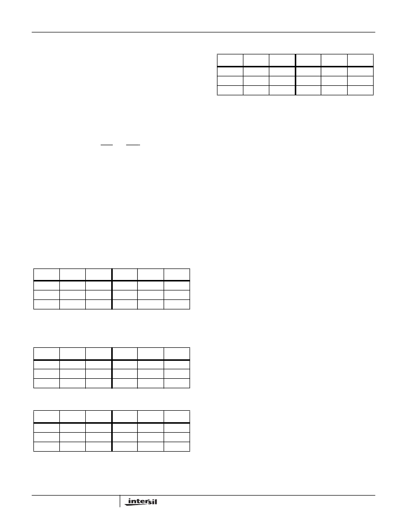
TABLE 2. CREST FACTOR PROGRAMMING RESISTOR FOR
V
BAT
= -80V
R
TRAP
CF
RMS
R
TRAP
CF
RMS
0
389
640
1.10
65.0
825
964
1095
1.25
57.6
1.15
62.6
1.30
55.4
1.20
60.0
1.35
53.3
TABLE 3. CREST FACTOR PROGRAMMING RESISTOR FOR
V
BAT
= -75V
R
TRAP
CF
RMS
R
TRAP
CF
RMS
0
500
791
1.10
60.9
1010
1190
1334
1.25
53.7
1.15
58.3
1.30
51.6
1.20
55.9
1.35
49.7
TABLE 4. CREST FACTOR PROGRAMMING RESISTOR FOR
V
BAT
= -65V
R
TRAP
CF
RMS
R
TRAP
CF
RMS
0
660
1040
1.10
52.5
1330
1600
1800
1.25
45.9
1.15
49.8
1.30
44.1
1.20
47.8
1.35
42.5
TABLE 5. CREST FACTOR PROGRAMMING RESISTOR FOR
V
BAT
= -60V
R
TRAP
CF
RMS
R
TRAP
CF
RMS
0
740
1129
1.10
48.2
1460
1760
2030
1.25
42.0
1.15
45.6
1.30
40.4
1.20
43.7
1.35
38.8
HC55171
相關(guān)PDF資料 |
PDF描述 |
|---|---|
| HC55171 | 5 REN Ringing SLIC for ISDN Modem/TA and WLL |
| HC55171CB | 5 REN Ringing SLIC for ISDN Modem/TA and WLL |
| HC55171CM | 5 REN Ringing SLIC for ISDN Modem/TA and WLL |
| HC55171IM | 5 REN Ringing SLIC for ISDN Modem/TA and WLL |
| HC55185BIM | VoIP Ringing SLIC Family |
相關(guān)代理商/技術(shù)參數(shù) |
參數(shù)描述 |
|---|---|
| HC55171IM | 制造商:INTERSIL 制造商全稱:Intersil Corporation 功能描述:5 REN Ringing SLIC for ISDN Modem/TA and WLL |
| HC5517B | 制造商:INTERSIL 制造商全稱:Intersil Corporation 功能描述:Low Cost 3 REN Ringing SLIC for ISDN Modem/TA and WL |
| HC5517B WAF | 制造商:Harris Corporation 功能描述: |
| HC5517BCB | 制造商:Rochester Electronics LLC 功能描述:- Bulk 制造商:Harris Corporation 功能描述: |
| HC5517BCB96S2495 | 制造商:Rochester Electronics LLC 功能描述:- Bulk |
發(fā)布緊急采購,3分鐘左右您將得到回復(fù)。