- 您現(xiàn)在的位置:買賣IC網(wǎng) > PDF目錄370460 > HD404652 (Hitachi,Ltd.) 4-Bit Single-Chip Microcomputer PDF資料下載
參數(shù)資料
| 型號: | HD404652 |
| 廠商: | Hitachi,Ltd. |
| 英文描述: | 4-Bit Single-Chip Microcomputer |
| 中文描述: | 4位單片機 |
| 文件頁數(shù): | 10/109頁 |
| 文件大小: | 430K |
| 代理商: | HD404652 |
第1頁第2頁第3頁第4頁第5頁第6頁第7頁第8頁第9頁當(dāng)前第10頁第11頁第12頁第13頁第14頁第15頁第16頁第17頁第18頁第19頁第20頁第21頁第22頁第23頁第24頁第25頁第26頁第27頁第28頁第29頁第30頁第31頁第32頁第33頁第34頁第35頁第36頁第37頁第38頁第39頁第40頁第41頁第42頁第43頁第44頁第45頁第46頁第47頁第48頁第49頁第50頁第51頁第52頁第53頁第54頁第55頁第56頁第57頁第58頁第59頁第60頁第61頁第62頁第63頁第64頁第65頁第66頁第67頁第68頁第69頁第70頁第71頁第72頁第73頁第74頁第75頁第76頁第77頁第78頁第79頁第80頁第81頁第82頁第83頁第84頁第85頁第86頁第87頁第88頁第89頁第90頁第91頁第92頁第93頁第94頁第95頁第96頁第97頁第98頁第99頁第100頁第101頁第102頁第103頁第104頁第105頁第106頁第107頁第108頁第109頁

HD404654 Series
10
$000
$003
PMRA $004
SM1A $005
SR1L $006
SR1U $007
TMA $008
MIS $00C
TMC1 $00D
TRCL/TWCL $00E
TRCU/TWCU $00F
TMD1 $010
TRDL/TWDL $011
TRDU/TWDU $012
$013
TMC2 $014
TMD2 $015
$016
CDR $017
CER $018
TGM $019
TGC $01A
$020
$023
PMRB $024
PMRC $025
$026
ESR2 $027
SM1B $028
SSR1 $029
SSR2 $02A
DCD0 $02C
DCD1 $02D
DCD2 $02E
DCR0 $030
DCR1 $031
DCR2 $032
DCR3 $033
DCR4 $034
$03F
Bit 3
Bit 2
Bit 1
Interrupt control bits area
: Not used
R4
2
/SI
1
R4
3
/SO
1
Serial transmit clock speed selection 1
Serial data register 1 (lower digit)
Serial data register 1 (upper digit)
Clock source selection (timer A)
2
1
*
SO
1
PMOS control
Clock source selection (timer C)
Timer C register (lower digit)
Timer C register (upper digit)
Clock source selection (timer D)
Timer D register (lower digit)
Timer D register (upper digit)
Interrupt frame period selection
1
Timer-C output mode selection
Timer-D output mode selection
3
*
Result of each analog input comparison
Register flag area
R4
0
/EVND
EVND detection edge selection
8
*
9
*
Port D
3
DCR
Port D
7
DCR
Port D
2
DCR
Port D
6
DCR
Port D
1
DCR
Port D
5
DCR
Port D
9
DCR
Port D
0
DCR
Port D
4
DCR
Port D
8
DCR
Port R1
3
DCR
Port R2
3
DCR
Port R3
3
DCR
Port R4
3
DCR
Port R1
2
DCR
Port R2
2
DCR
Port R3
2
DCR
Port R4
2
DCR
Port R1
1
DCR
Port R2
1
DCR
Port R3
1
DCR
Port R4
1
DCR
Port R0
0
DCR
Port R1
0
DCR
Port R2
0
DCR
Port R3
0
DCR
Port R4
0
DCR
D
12
/
STOPC
D
13
/
INT
0
R0
0
/
INT
1
R4
1
/
SCK
1
Bit 0
System clock selection
4
*
5
*
6
*
7
*
TONEC output frequency
TONER output frequency
DTMF enable
10
1. Auto-reload on/off
2. Pull-up MOS control
3. Input capture selection
4. Comparator switch
5. Port/comparator selection
6. TONEC output control
7. TONER output control
8. SO
output level control in idle states
9. Serial clock source selection 1
10. System clock selection
Notes:
*
*
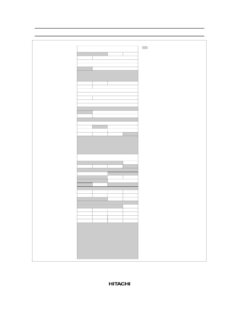
Figure 5 Special Function Register Area
相關(guān)PDF資料 |
PDF描述 |
|---|---|
| HD404652H | RES T 0.2E 5W 1% |
| HD404652S | 4-Bit Single-Chip Microcomputer |
| HD404654 | RESISTOR, 0.10 OHM 5W |
| HD404654H | 4-Bit Single-Chip Microcomputer |
| HD404654S | 4-Bit Single-Chip Microcomputer |
相關(guān)代理商/技術(shù)參數(shù) |
參數(shù)描述 |
|---|---|
| HD404652H | 制造商:HITACHI 制造商全稱:Hitachi Semiconductor 功能描述:4-Bit Single-Chip Microcomputer |
| HD404652S | 制造商:HITACHI 制造商全稱:Hitachi Semiconductor 功能描述:4-Bit Single-Chip Microcomputer |
| HD404654 | 制造商:HITACHI 制造商全稱:Hitachi Semiconductor 功能描述:4-Bit Single-Chip Microcomputer |
| HD404654H | 制造商:HITACHI 制造商全稱:Hitachi Semiconductor 功能描述:4-Bit Single-Chip Microcomputer |
| HD404654S | 制造商:HITACHI 制造商全稱:Hitachi Semiconductor 功能描述:4-Bit Single-Chip Microcomputer |
發(fā)布緊急采購,3分鐘左右您將得到回復(fù)。