- 您現(xiàn)在的位置:買賣IC網(wǎng) > PDF目錄370701 > HSMx-C110 Surface Mount Chip LEDs(表貼型芯片LED) PDF資料下載
參數(shù)資料
| 型號(hào): | HSMx-C110 |
| 英文描述: | Surface Mount Chip LEDs(表貼型芯片LED) |
| 中文描述: | 表面貼裝芯片發(fā)光二極管(表貼型芯片發(fā)光二極管) |
| 文件頁數(shù): | 8/8頁 |
| 文件大?。?/td> | 222K |
| 代理商: | HSMX-C110 |
Notes:
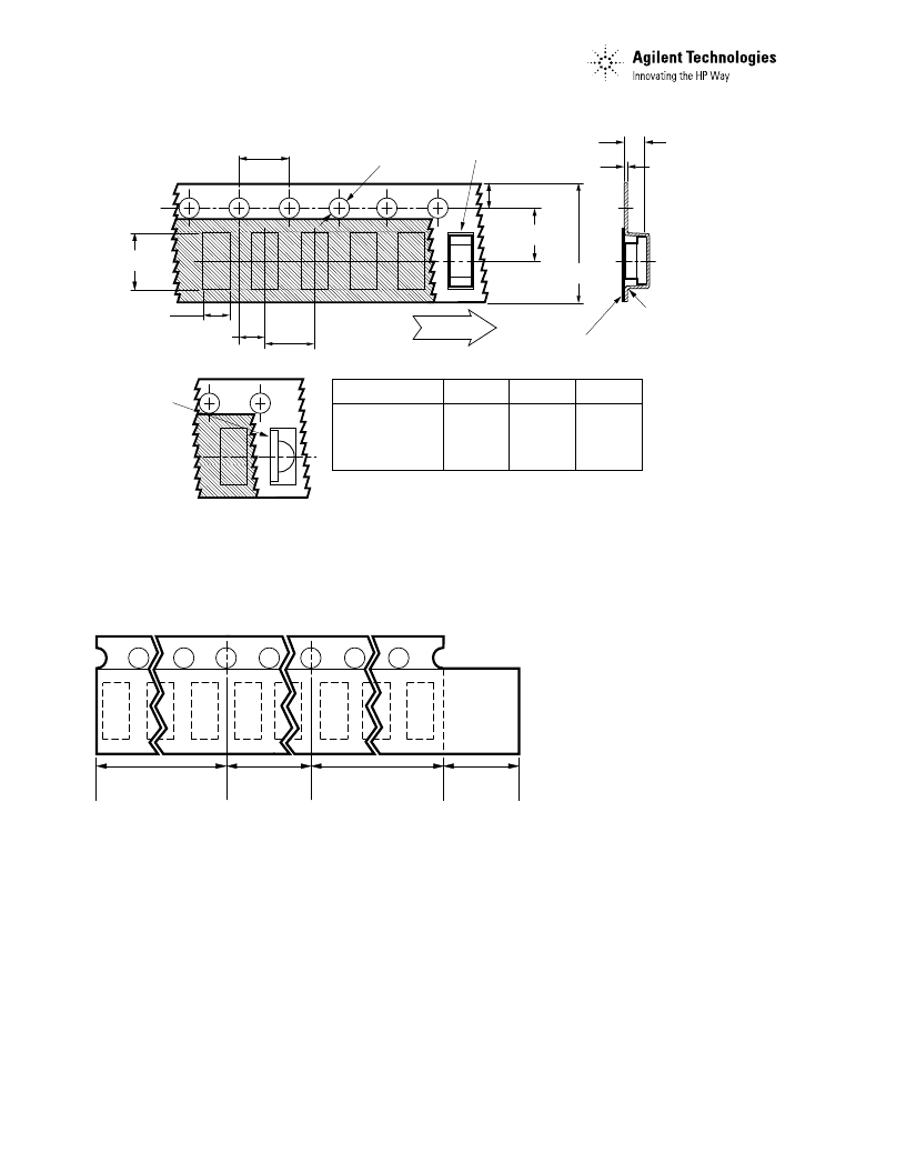
1. All dimensions in millimeters (inches).
2. Tolerance is
±
0.1 mm (
±
0.004 in.)unless otherwise specified.
Figure 14. Tape Dimensions.
Figure 15. Tape Leader and Trailer Dimensions.
Convective IR Reflow
Soldering
For more information on IR
reflow soldering, refer to
Application Note 1060,
Surface
Mounting SMT LED Indicator
Components.
END
START
THERE SHALL BE A
MINIMUM OF 160 mm
(6.3 INCH) OF EMPTY
COMPONENT POCKETS
SEALED WITH COVER
TAPE.
MOUNTED WITH
COMPONENTS
THERE SHALL BE A
MINIMUM OF 160 mm
(6.3 INCH) OF EMPTY
COMPONENT POCKETS
SEALED WITH COVER
TAPE.
MINIMUM OF
230 mm
(9.05 INCH)
MAY CONSIST
OF CARRIER
AND/OR
COVER TAPE.
8.00 ± 0.30
(0.315 ± 0.012)
USER FEED
DIRECTION
DIM. A
(SEE TABLE 1)
3.50 ± 0.05
(0.138 ± 0.002)
1.75 (0.069)
DIM. C
(SEE TABLE 1)
0.20 ± 0.05
(0.008 ± 0.002)
CARRIER TAPE
COVER TAPE
DIM. B
(SEE TABLE 1)
4.00 (0.157)
2.00 ± 0.05
(0.079 ± 0.002)
4.00 (0.157)
1.50 (0.059)
HSMx-C150 SERIES 3.75 (0.148) 2.10 (0.083) 1.30 (0.051)
HSMx-C170 SERIES 2.40 (0.094) 1.60 (0.063) 1.20 (0.047)
HSMx-C190 SERIES 1.85 (0.073) 1.00 (0.039) 1.20 (0.047)
HSMx-C110 SERIES 3.35 (0.132) 1.85 (0.073) 1.20 (0.047)
TABLE 1
DIMENSIONS IN MILLIMETERS (INCHES)
DIM. A
± 0.10 (0.004)
PART NUMBER
CATHODE
DIM. B
± 0.10 (0.004)
DIM. C
± 0.10 (0.004)
HSMx-C110
POSITION ON
CARRIER TAPE
www.semiconductor.agilent.com
Data subject to change.
Copyright 2000 Agilent Technologies, Inc.
Obsoletes 5980-1041E
5980-2430E (9/00)
Storage Condition: 5 to 30 C
@ 60% RH max.
Baking is required under the
condition:
a) the blue silica gel indicator
becoming white/transparent color
b) the pack has been opened for
more than 1 week
Baking recommended condition:
60 +/– 5C for 20 hours.
相關(guān)PDF資料 |
PDF描述 |
|---|---|
| HSMx-C260 | Surface Mount Chip LEDs(表貼型芯片LED) |
| HSMx-C650 | Surface Mount Chip LEDs(表貼型芯片LED) |
| HSMF-C655 | Surface Mount Chip LEDs(表貼型芯片LED) |
| HSMx-C670 | Surface Mount Chip LEDs(表貼型芯片LED) |
| HSMx-C660 | Right Angle Surface Mount Chip LEDs(直角表面封裝LED) |
相關(guān)代理商/技術(shù)參數(shù) |
參數(shù)描述 |
|---|---|
| HSMX-C120 | 制造商:AGILENT 制造商全稱:AGILENT 功能描述:Surface Mount Chip LEDs |
| HSMX-C150 | 制造商:HP 制造商全稱:Agilent(Hewlett-Packard) 功能描述:SMT ChipLEDs |
| HSMX-C170 | 制造商:HP 制造商全稱:Agilent(Hewlett-Packard) 功能描述:SMT ChipLEDs |
| HSMX-C177 | 制造商:AGILENT 制造商全稱:AGILENT 功能描述:Agilent HSMx-C1xx High Performance Chip LED |
| HSMX-C190 | 制造商:HP 制造商全稱:Agilent(Hewlett-Packard) 功能描述:SMT ChipLEDs |
發(fā)布緊急采購,3分鐘左右您將得到回復(fù)。