- 您現(xiàn)在的位置:買賣IC網(wǎng) > PDF目錄371896 > HSP43216JC-52 (INTERSIL CORP) Halfband Filter PDF資料下載
參數(shù)資料
3-204
If internal multiplexing is selected (INT/EXT = 1), the data
streaminputthroughAIN0-15isfedtoboththeupperandlower
processing legs as shown in Figure 11A. The output of each
processing leg is then multiplexed together to produce the
interpolated sample stream at twice the input sample rate. In
this mode the device is clocked at the interpolated data rate to
support the multiplexing of each processing leg’s output into a
single data stream. The upper and lower processing legs each
run at the input data rate of CLK/2 as indicated by the “
”
marking the various registers and processing elements in
Figure 11A. In this mode, data samples are clocked into the
part on every other
rising edge
of CLK. The SYNC signal is
used to specify which set of CLK cycles are used to register
data at the part’s input. Specifically, every other rising edge of
CLK starting one CLK after the assertion of SYNC will be used
to clock data into the part. With internal multiplexing the
minimum pipeline delay through the upper processing leg is 15
CLK’s and the pipeline delay through the lower processing leg
is 48 CLK’s, (2[19+3]+4).
If external multiplexing is selected (INT/EXT = 0), the upper
and lower processing legs are output through AOUT0-15
and BOUT0-15 for multiplexing into a single data stream off
chip.This allows the processing legs to run at the maximum
clock rate which coincides with an interpolated output data
rate of 104 MSPS.
NOTE: The samples output on
BOUT0-15 precede those on AOUT0-15 in sample order.
This requires a multiplexing scenario in which BOUT0-15 is
selected before AOUT0-15. With external multiplexing, the
minimum pipeline delay through the upper processing leg is
9 CLK’s and the pipeline delay through the lower processing
leg is 26 CLK’s as shown in Figure 11B. In this mode SYNC
has no effect on part operation.
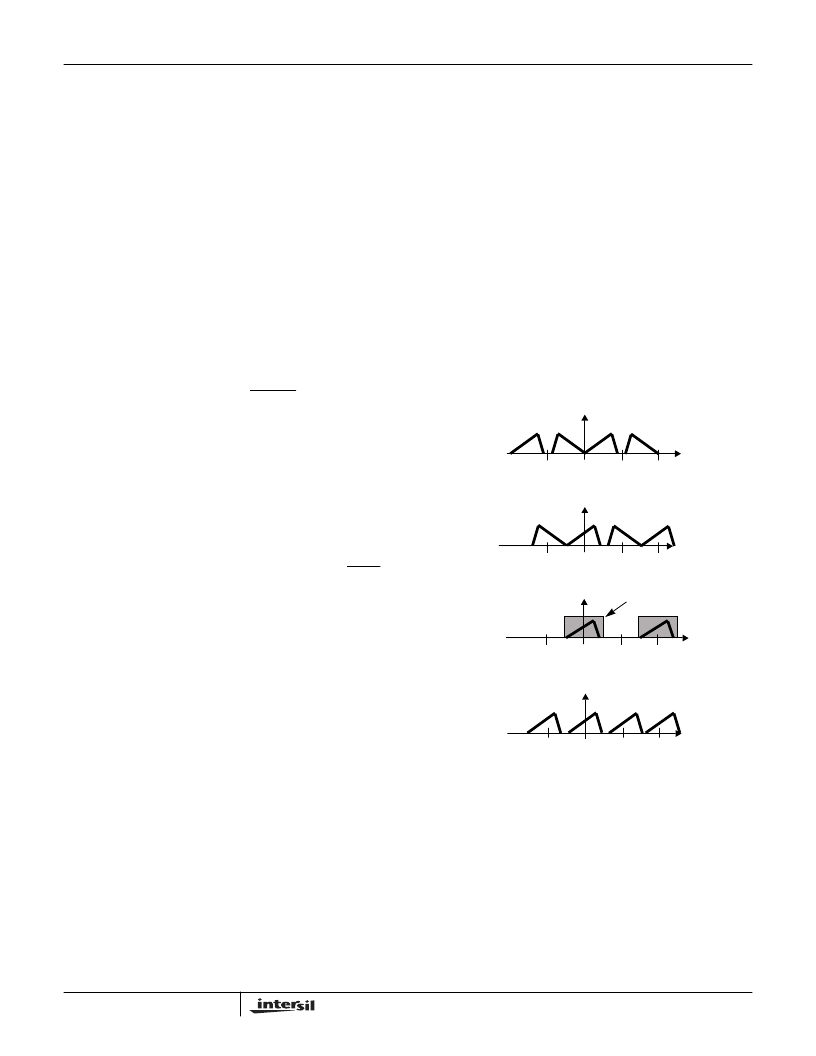
Down Convert and Decimate Mode (MODE1-0 = 10)
In Down Convert and Decimate Mode a real input signal is
spectrally shifted -f
S
/4 which centers the upper sideband at
DC. This operation produces real and imaginary
components which are each filtered and decimated by
identical 67-tap halfband filters. For added flexibility, a
positive f
S
/4 spectral shift may be selected which centers
the lower sideband at DC. The direction of the spectral shift
is selected via USB/LSB as described in the Quadrature
Down Convert section. A spectral representation of the
down convert and decimate operation is shown in Figure 12
(USB/LSB = 1).
NOTE: Each of the complex terms
output by the Filter Processor are scaled by two to
compensate for the attenuation of one half introduced
by the down conversion process.
The Down Convert and Decimate mode is most easily
understood by first considering the transversal
implementation using a 7 tap filter as shown in Figure 13.
By examining the combination of down conversion, filtering
and decimation, it is seen that the real outputs are only
dependent on the sum-of-products for the even indexed
samples and filter coefficients, and the imaginary outputs
are only a function of the sum-of-products for the odd
indexed samples and filter coefficients. This computational
partitioning allows the quadrature filters required after down
conversion to be realized using the same poly-phase
processing elements used in the previous two modes.
A functional block diagram of the polyphase implementation
is shown in Figure 14. In this implementation, the input data
stream is broken into even and odd sample streams and
processed independently by the even and odd tap filters. By
decomposing the sample stream into even and odd samples,
the zero mix terms produced by the down convert LO drop
out of the data streams, and the output of each of the filters
represent the decimated data streams for both the real and
imaginary outputs.
INPUT SIGNAL SPECTRUM
DOWN CONVERTED SIGNAL
FILTERED SIGNAL
FILTER PASSBAND
DECIMATED OUTPUT SIGNAL SPECTRUM
0
f
S
/2
f
S
-f
S
/2
0
f
S
/2
f
S
-f
S
/2
0
f
S
/2
f
S
-f
S
/2
0
f
’S
2f
’S
-f
’S
f
S
= INPUT SAMPLE RATE
f
’S
= DECIMATED SAMPLE RATE, f
S
/2
FIGURE 12. DOWN CONVERT AND DECIMATE OPERATION
HSP43216
相關(guān)PDF資料 |
PDF描述 |
|---|---|
| HSP43220JC-15 | Circular Connector; MIL SPEC:MIL-C-5015; Body Material:Metal; Series:GT; No. of Contacts:4; Connector Shell Size:24; Connecting Termination:Solder; Circular Shell Style:Box Mount Receptacle; Body Style:Straight |
| HSP43220GC-25 | Decimating Digital Filter |
| HSP43220GC-33 | Decimating Digital Filter |
| HSP43220VC-33 | Decimating Digital Filter |
| HSP43220 | RESISTOR 47 OHM 20W TO220 |
相關(guān)代理商/技術(shù)參數(shù) |
參數(shù)描述 |
|---|---|
| HSP43216JC-52S2485 | 制造商:Rochester Electronics LLC 功能描述:- Bulk |
| HSP43216JC-52Z | 功能描述:有源濾波器 W/ANNEAL HALFB& INTE RP/DECIMATE FILTER RoHS:否 制造商:Maxim Integrated 通道數(shù)量:1 截止頻率:150 KHz 電源電壓-最大:11 V 電源電壓-最小:4.74 V 最大工作溫度:+ 85 C 安裝風(fēng)格:Through Hole 封裝 / 箱體:PDIP N 封裝:Tube |
| HSP43216JI-52 | 制造商:Rochester Electronics LLC 功能描述:- Bulk |
| HSP43216VC-52 | 功能描述:有源濾波器 HALFBAND FILTER 100 PIN PQFP,COMM RoHS:否 制造商:Maxim Integrated 通道數(shù)量:1 截止頻率:150 KHz 電源電壓-最大:11 V 電源電壓-最小:4.74 V 最大工作溫度:+ 85 C 安裝風(fēng)格:Through Hole 封裝 / 箱體:PDIP N 封裝:Tube |
| HSP43216VC-52Z | 功能描述:有源濾波器 W/ANNEAL HALFB & FILER 100 PIN PQFP RoHS:否 制造商:Maxim Integrated 通道數(shù)量:1 截止頻率:150 KHz 電源電壓-最大:11 V 電源電壓-最小:4.74 V 最大工作溫度:+ 85 C 安裝風(fēng)格:Through Hole 封裝 / 箱體:PDIP N 封裝:Tube |
發(fā)布緊急采購,3分鐘左右您將得到回復(fù)。