- 您現(xiàn)在的位置:買賣IC網(wǎng) > PDF目錄370723 > HTR6516R (Hitachi,Ltd.) SFP TRANSCEIVER for Gigabit Ethernet Fibre Channel PDF資料下載
參數(shù)資料
| 型號: | HTR6516R |
| 廠商: | Hitachi,Ltd. |
| 英文描述: | SFP TRANSCEIVER for Gigabit Ethernet Fibre Channel |
| 中文描述: | SFP收發(fā)器千兆以太網(wǎng)光纖通道 |
| 文件頁數(shù): | 11/16頁 |
| 文件大小: | 569K |
| 代理商: | HTR6516R |

Page 10 of 15
12.Enhanced Functions
E nhanced functions interface uses the 2 wire address 1010001X (0xA2). Memory contents of
enhanced functions are shown in Table 6.1.
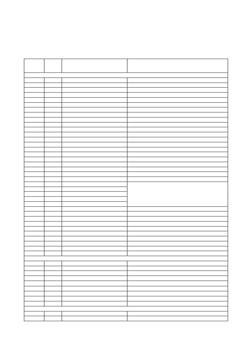
Table 6.1 Memory Contents / 2 wire address 1010001X (0xA2)
Data
Address
Field
Size
(Bytes)
Name
Remark
CONSTANTS FIELDS
00-01
02-03
04-05
06-07
08-09
10-11
12-13
14-15
16-17
18-19
20-21
22-23
24-25
26-27
28-29
30-31
32-33
34-35
36-37
38-39
40-55
56-59
60-63
64-67
68-71
72-75
76-77
78-79
80-81
82-83
84-85
86-87
88-89
90-91
92-94
95
2
2
2
2
2
2
2
2
2
2
2
2
2
2
2
2
2
2
2
2
16
4
4
4
4
4
2
2
2
2
2
2
2
2
3
1
Temperature High Alarm
Temperature Low Alarm
Temperature High Warning
Temperature Low Warning
Vcc High Alarm
Vcc Low Alarm
Vcc High Warning
Vcc Low Warning
Laser Bias High Alarm
Laser Bias Low Alarm
Laser Bias High Warning
Laser Bias Low Warning
Tx Power High Alarm
Tx Power Low Alarm
Tx Power High Warning
Tx Power Low Warning
Rx Power High Alarm
Rx Power Low Alarm
Rx Power High Warning
Rx Power Low Warning
Reserved
Rx Power Calibration Data R
4
Rx Power Calibration Data R
3
Rx Power Calibration Data R
2
Rx Power Calibration Data R
1
Rx Power Calibration Data R
0
Laser Bias Calibration Data B
1
Laser Bias Calibration Data B
0
Tx Power Calibration Data P
1
Tx Power Calibration Data P
0
Temp. Calibration Data T
1
Temp. Calibration Data T
0
Vcc Calibration Data V
1
Vcc Calibration Data V
0
Reserved
Checksum
Set to 85 deg-C
Set to -15 deg-C
Set to 80 deg-C
Set to -5 deg-C
Set to 3.6 V
Set to 3.0 V
Set to 3.5 V
Set to 3.1 V
Various at each device
Various at each device
Various at each device
Various at each device
Manufacture measurement plus 3 dB
Manufacture measurement minus 3dB
Manufacture measurement plus 2 dB
Manufacture measurement minus 2dB
Maximum input power plus 1 dB
Minimum input power minus 2 dB
Maximum input power plus 0.5 dB
Minimum input power minus 1 dB
All bytes set to 0x00
Single
precision
values at each device for incompatibility with “internal
calibration”)
floating-point
numbers
(various
Unsigned fixed-point number (set to 1) *
16-bit signed 2's complement number (set to 0) *
Unsigned fixed-point number (set to 1) *
16-bit signed 2's complement number (set to 0) *
Unsigned fixed-point number (set to 1) *
16-bit signed 2's complement number (set to 0) *
Unsigned fixed-point number (set to 1) *
16-bit signed 2's complement number (set to 0) *
All bytes set to 0x00
Low order 8 bits of the sum of byte 0-94.
VARIABLES FIELDS
Measured Temperature
Raw 16-bit A/D value (see Table 6.2)
Measured Vcc
Raw 16-bit A/D value (see Table 6.2)
Measured Laser Bias
Raw 16-bit A/D value (see Table 6.2)
Measured Tx Power
Raw 16-bit A/D value (see Table 6.2)
Measured Rx Power
Raw 16-bit A/D value (see Table 6.2)
Reserved
All bytes set to 0x00
Logic States
See Table 6.4
AD Updated
See Table 6.4
Alarm and Warning Flags
See Table 6.5
VE NDOR SPE CIFIC FIE LDS
Vendor Specific
Do not access in order to operate normally
No physical memory
96-97
98-99
100-101
102-103
104-105
106-109
110
111
112-119
2
2
2
2
2
4
1
1
8
120-127
128-255
4
136
* Slopes B
1
=P
1
=T
1
=V
1
=1, intercepts B
0
=P
0
=T
0
=V
0
=0, for compatibility with “internal calibration”.
相關(guān)PDF資料 |
PDF描述 |
|---|---|
| HTR6516R2 | SFP TRANSCEIVER for Gigabit Ethernet Fibre Channel |
| HTR6516 | SFP TRANSCEIVER for Gigabit Ethernet Fibre Channel |
| HTR6545 | SFF TRANSCEIVER |
| HTY75-P | Current Transducer HTY 50~100-P |
| HTY50-P | Current Transducer HTY 50~100-P |
相關(guān)代理商/技術(shù)參數(shù) |
參數(shù)描述 |
|---|---|
| HTR6516R2 | 制造商:HITACHI 制造商全稱:Hitachi Semiconductor 功能描述:SFP TRANSCEIVER for Gigabit Ethernet Fibre Channel |
| HTR6543 | 制造商:Hitachi 功能描述: |
| HTR6545 | 制造商:HITACHI 制造商全稱:Hitachi Semiconductor 功能描述:SFF TRANSCEIVER |
| HTRC110 | 制造商:PHILIPS 制造商全稱:NXP Semiconductors 功能描述:HITAG reader chip |
| HTRC11001 | 制造商:PHILIPS 制造商全稱:NXP Semiconductors 功能描述:HITAG reader chip |
發(fā)布緊急采購,3分鐘左右您將得到回復(fù)。