- 您現(xiàn)在的位置:買賣IC網(wǎng) > PDF目錄370723 > HTR6516R (Hitachi,Ltd.) SFP TRANSCEIVER for Gigabit Ethernet Fibre Channel PDF資料下載
參數(shù)資料
| 型號: | HTR6516R |
| 廠商: | Hitachi,Ltd. |
| 英文描述: | SFP TRANSCEIVER for Gigabit Ethernet Fibre Channel |
| 中文描述: | SFP收發(fā)器千兆以太網(wǎng)光纖通道 |
| 文件頁數(shù): | 3/16頁 |
| 文件大?。?/td> | 569K |
| 代理商: | HTR6516R |

Page 2 of 15
4. Absolute Maximum Ratings
Stresses in excess of the ratings listed in Table 1 can cause permanent damage to the device
and affect device reliability. Functional operation of the device is not implied at any condition
in excess of those given in the operating specification.
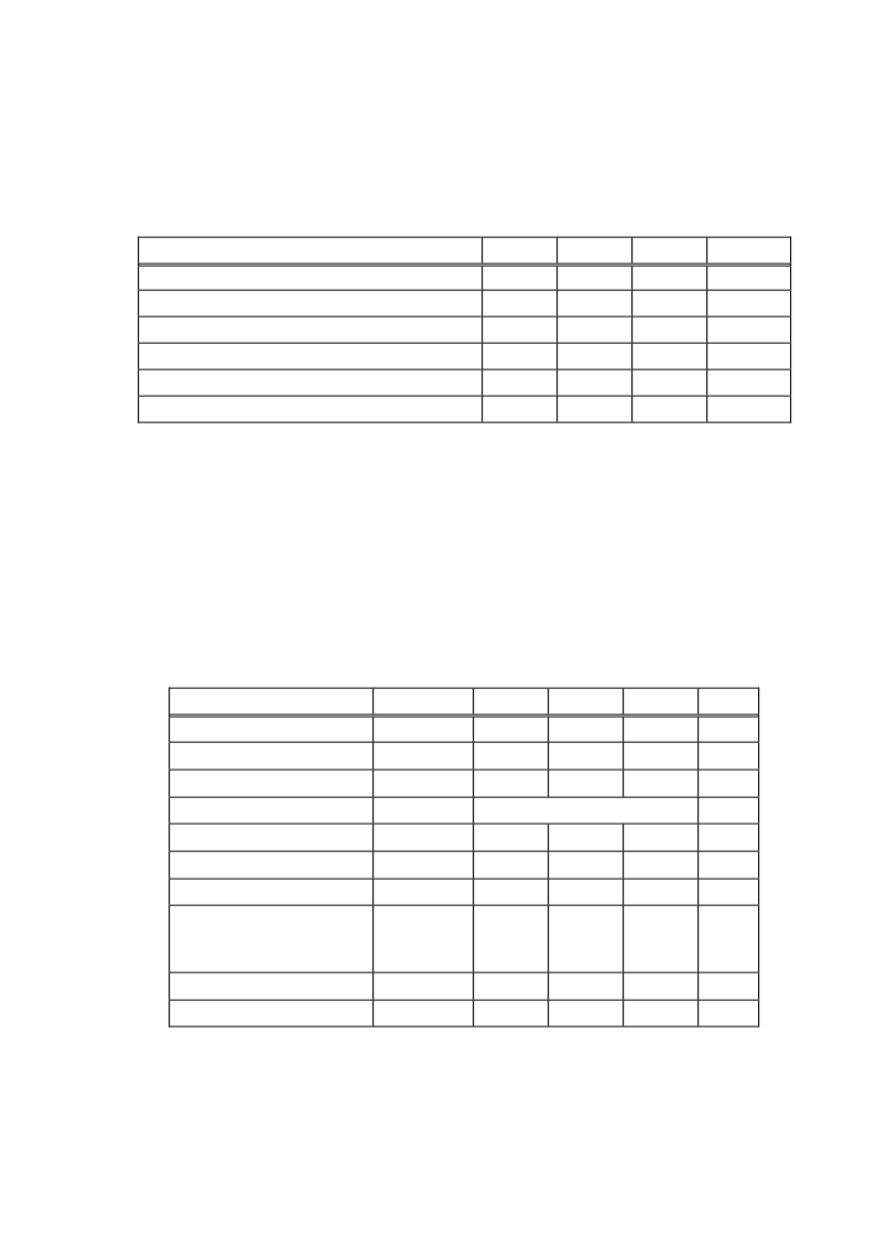
Table 1. Absolute Maximum Ratings
Parameter
Symbol
Min.
Max.
Unit
Supply Voltage
V
CC
0
4.0
V
Data Input Voltage
V
IN
V
E E
V
CC
+0.3
V
Receiver Optical Input Power
P
in
-
+3
dBm
Operating Ambient Temperature
T
A
-5
70
deg-C
Storage Case Temperature
Tstg
-40
85
deg-C
Operating Relative Humidity (non-condensing)
H
A
5
85
%
5. Optical and Electrical Characteristics of Transmitter Portion
Optical and electrical characteristics of transmitter portion are shown in Table 2. Unless
otherwise stated, minimum and maximum values are specified over the operating ambient
temperature, and humidity ranges, DC power supply voltage range, from beginning to end of life,
using 2
7
-1 pseudo random bit stream with a 50% duty factor.
The logic sense for the DATA input is such that a logic “1”(High) corresponds to the maximum
level of an amplitude modulated light source (Light on), while a logic “0”(Low) corresponds to a
minimum level of an amplitude modulated light source (Light off).
Table 2. Transmitter Optical and Electrical Characteristics
Parameter
Symbol
Min
Typ
Max
Unit
Optical Output Power
Po
-9
-
-3
dBm
Center Wavelength
λ
1290
-
1340
nm
Spectral Width(RMS)
λ
-
-
2.8
nm
Eye Mask
-
IE E E 802.3z
-
Extinction Ratio
-
9.0
-
-
dB
DC Power Supply Voltage
Vcc
3.135
3.3
3.465
V
DC Power Supply Current
Icc
-
-
100
mA
Data Input Voltage
a
Diff’l Input Swing
Diff’l Input Impedance
V
ID SWING
Z
ID
500
85
-
100
-
2400
115
mV
p-p
Tx Disable Voltage
V
D
Vcc-1.3
-
Vcc
V
Tx E nable Voltage
V
E N
V
E E
-
V
E E
+0.8
V
a. AC coupled inside the module
相關(guān)PDF資料 |
PDF描述 |
|---|---|
| HTR6516R2 | SFP TRANSCEIVER for Gigabit Ethernet Fibre Channel |
| HTR6516 | SFP TRANSCEIVER for Gigabit Ethernet Fibre Channel |
| HTR6545 | SFF TRANSCEIVER |
| HTY75-P | Current Transducer HTY 50~100-P |
| HTY50-P | Current Transducer HTY 50~100-P |
相關(guān)代理商/技術(shù)參數(shù) |
參數(shù)描述 |
|---|---|
| HTR6516R2 | 制造商:HITACHI 制造商全稱:Hitachi Semiconductor 功能描述:SFP TRANSCEIVER for Gigabit Ethernet Fibre Channel |
| HTR6543 | 制造商:Hitachi 功能描述: |
| HTR6545 | 制造商:HITACHI 制造商全稱:Hitachi Semiconductor 功能描述:SFF TRANSCEIVER |
| HTRC110 | 制造商:PHILIPS 制造商全稱:NXP Semiconductors 功能描述:HITAG reader chip |
| HTRC11001 | 制造商:PHILIPS 制造商全稱:NXP Semiconductors 功能描述:HITAG reader chip |
發(fā)布緊急采購,3分鐘左右您將得到回復(fù)。