- 您現(xiàn)在的位置:買賣IC網(wǎng) > PDF目錄377500 > IR3637STRPBF (International Rectifier) 1% ACCURATE SYNCHRONOUS PWM CONTROLLER PDF資料下載
參數(shù)資料
| 型號: | IR3637STRPBF |
| 廠商: | International Rectifier |
| 英文描述: | 1% ACCURATE SYNCHRONOUS PWM CONTROLLER |
| 中文描述: | 1%準確的同步PWM控制器 |
| 文件頁數(shù): | 5/21頁 |
| 文件大小: | 655K |
| 代理商: | IR3637STRPBF |

IR3637SPBF
5
Rev. 1.1
06/16/05
www.irf.com
THEORY OF OPERATION
Soft-Start
The IR3637 has a programmable soft-start to control the
output voltage rise and limit the current surge at the start-
up. To ensure correct start-up, the soft-start sequence
initiates when the Vc and Vcc rise above their threshold
(3.3V and 4.2V respectively) and generates the Power
On Reset (POR) signal. Soft-start function operates by
sourcing an internal current to charge an external ca-
pacitor to about 3V. Initially, the soft-start function clamps
the E/A’s output of the PWM converter and disables the
short circuit protection. During the power up, the output
starts at zero and voltage at Fb is below 0.4V. The feed-
back UVLO is disabled during this time by injecting a
current (64
μ
A) into the Fb. This generates a voltage
about 1.6V (64
μ
A
×
25K) across the negative input of E/
A and positive input of the feedback UVLO comparator
(see Figure 3).
The magnitude of this current is inversely proportional to
the voltage at soft-start pin.
The 20
μ
A current source starts to charge up the exter-
nal capacitor. In the mean time, the soft-start voltage
ramps up, the current flowing into Fb pin starts to de-
crease linearly and so does the voltage at the positive
pin of feedback UVLO comparator and the voltage nega-
tive input of E/A.
When the soft-start capacitor is around 1V, the current
flowing into the Fb pin is approximately 32
μ
A. The volt-
age at the positive input of the E/A is approximately:
32
μ
A
×
25K = 0.8V
The E/A will start to operate and the output voltage starts
to increase. As the soft-start capacitor voltage contin-
ues to go up, the current flowing into the Fb pin will keep
decreasing. Because the voltage at pin of E/A is regu-
lated to reference voltage 0.8V, the voltage at the Fb is:
The feedback voltage increases linearly as the injecting
current goes down. The injecting current drops to zero
when soft-start voltage is around 2V and the output volt-
age goes into steady state.
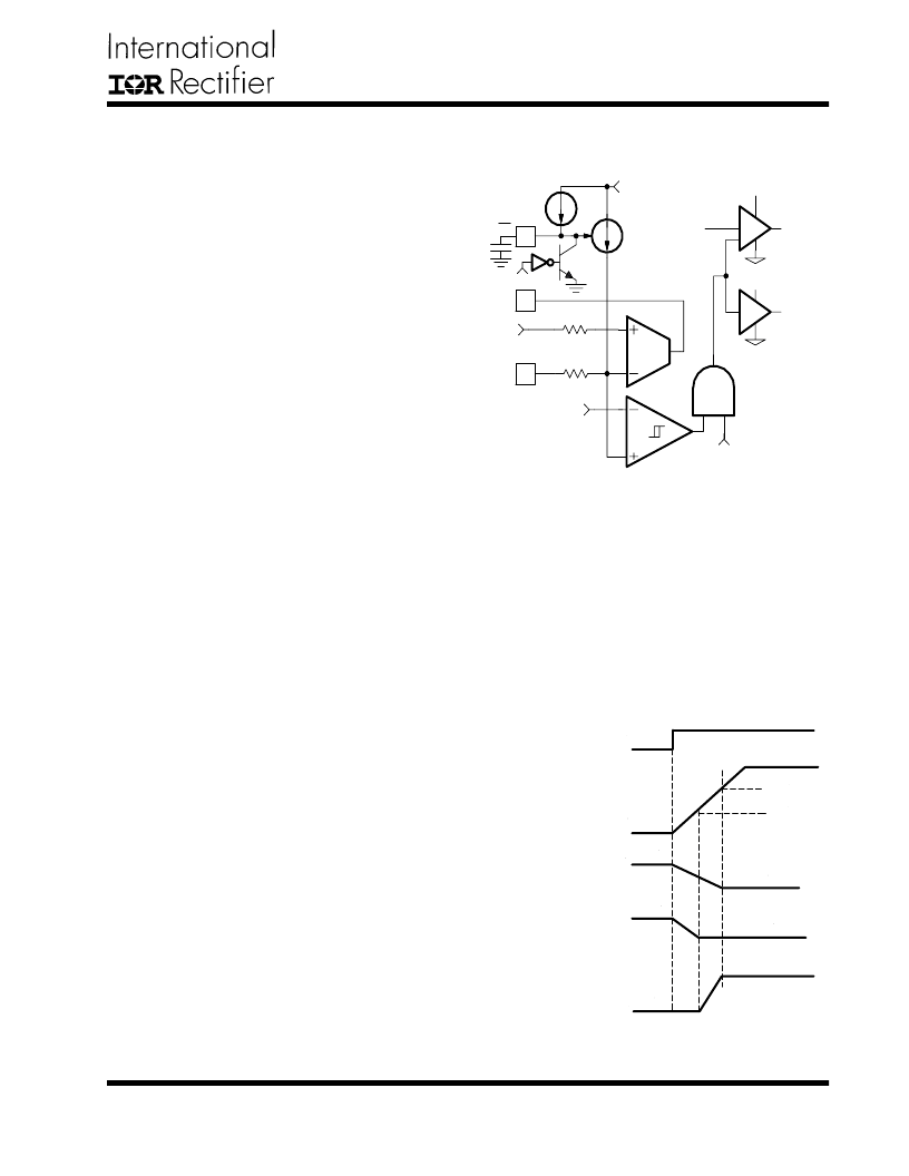
As shown in Figure 4, the positive pin of feedback UVLO
comparator is always higher than 0.4V, therefore, feed-
back UVLO is not functional during soft-start.
25uA
64uA
Max
POR
Error Amp
64uA
×
25K=1.6V
When SS=0
POR
0.4V
Feeback
UVLO Comp
SS/SD
Fb
Comp
25K
0.8V
25K
HDrv
LDrv
3V
V
FB
= 0.8-25K
×
(Injected Current)
The output start-up time is the time period when soft-
start capacitor voltage increases from 1V to 2V. The start-
up time will be dependent on the size of the external
soft-start capacitor. The start-up time can be estimated
by:
25
μ
A
×
T
START
/C
SS
= 2V-1V
For a given start up time, the soft-start capacitor can be
estimated as:
Soft-Start
Voltage
Voltage at negative input
of Error Amp and Feedback
UVLO comparator
Voltage at Fb pin
Current flowing
into Fb pin
64uA
0uA
0V
0.8V
1.6V
0.8V
0V
3V
2V
1V
Output of UVLO
POR
C
SS
25
μ
A
×
T
START
/1V
Figure 3 - Soft-start circuit for IR3637.
Figure 4 - Theoretical operational waveforms
during soft-start.
相關PDF資料 |
PDF描述 |
|---|---|
| IR3637SPBF | 1% ACCURATE SYNCHRONOUS PWM CONTROLLER |
| IR3638SPBF | HIGH FREQUENCY SYNCHRONOUS PWM BUCK CONTROLLER FOR TRACKING APPLIACTIONS |
| IR3651SPBF | HIGH VOLTAGE SYNCHRONOUS PWM BUCK CONTROLLER |
| IR3651STRPBF | HIGH VOLTAGE SYNCHRONOUS PWM BUCK CONTROLLER |
| IR3811MPBF | HIGHLY INTEGRATED 7A WIDE-INPUT VOLTAGE, SYNCHRONOUS BUCK REGULATOR |
相關代理商/技術參數(shù) |
參數(shù)描述 |
|---|---|
| IR3638 | 制造商:ONSEMI 制造商全稱:ON Semiconductor 功能描述:High Frequency Synchronous |
| IR3638DR2G | 制造商:ON Semiconductor 功能描述: |
| IR3638SPBF | 制造商:IRF 制造商全稱:International Rectifier 功能描述:HIGH FREQUENCY SYNCHRONOUS PWM BUCK CONTROLLER FOR TRACKING APPLIACTIONS |
| IR3638STRPBF | 功能描述:電壓模式 PWM 控制器 HI FREQ SYNC PWM 400kHz 0.6V Track RoHS:否 制造商:Texas Instruments 輸出端數(shù)量:1 拓撲結構:Buck 輸出電壓:34 V 輸出電流: 開關頻率: 工作電源電壓:4.5 V to 5.5 V 電源電流:600 uA 最大工作溫度:+ 125 C 最小工作溫度:- 40 C 封裝 / 箱體:WSON-8 封裝:Reel |
| IR3640MPBF | 功能描述:IC REG CTRLR BUCK PWM VM 20-MLPQ RoHS:是 類別:集成電路 (IC) >> PMIC - 穩(wěn)壓器 - DC DC 切換控制器 系列:- 標準包裝:4,000 系列:- PWM 型:電壓模式 輸出數(shù):1 頻率 - 最大:1.5MHz 占空比:66.7% 電源電壓:4.75 V ~ 5.25 V 降壓:是 升壓:無 回掃:無 反相:無 倍增器:無 除法器:無 Cuk:無 隔離:無 工作溫度:-40°C ~ 85°C 封裝/外殼:40-VFQFN 裸露焊盤 包裝:帶卷 (TR) |
發(fā)布緊急采購,3分鐘左右您將得到回復。