- 您現(xiàn)在的位置:買賣IC網(wǎng) > PDF目錄385446 > IRHF57230SE (International Rectifier) RADIATION HARDENED POWER MOSFET THRU-HOLE ( TO-39) PDF資料下載
參數(shù)資料
| 型號(hào): | IRHF57230SE |
| 廠商: | International Rectifier |
| 英文描述: | RADIATION HARDENED POWER MOSFET THRU-HOLE ( TO-39) |
| 中文描述: | 抗輻射功率MOSFET的通孔(到39) |
| 文件頁(yè)數(shù): | 3/8頁(yè) |
| 文件大?。?/td> | 137K |
| 代理商: | IRHF57230SE |
www.irf.com
3
IRHF57230SE, JANSR2N7498T2
Table 1. Electrical Characteristics @ Tj = 25°C, Post Total Dose Irradiation
International Rectifier Radiation Hardened MOSFETs are tested to verify their radiation hardness capability.
The hardness assurance program at International Rectifier is comprised of two radiation environments.
Every manufacturing lot is tested for total ionizing dose (per notes 5 and 6) using the TO-3 package. Both
pre- and post-irradiation performance are tested and specified using the same drive circuitry and test
conditions in order to provide a direct comparison.
Radiation Characteristics
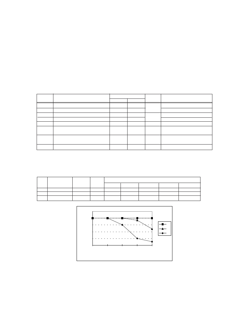
Fig a.
Single Event Effect, Safe Operating Area
International Rectifier radiation hardened MOSFETs have been characterized in heavy ion environment for
Single Event Effects (SEE). Single Event Effects characterization is illustrated in Fig. a and Table 2.
Table 2. Single Event Effect Safe Operating Area
For footnotes refer to the last page
Parameter
100K Rads (Si)
Min
200
2.0
—
—
—
Units
Test Conditions
Max
—
4.5
100
-100
10
BV
DSS
V
GS(th)
I
GSS
I
GSS
I
DSS
R
DS(on)
Drain-to-Source Breakdown Voltage
Gate Threshold Voltage
Gate-to-Source Leakage Forward
Gate-to-Source Leakage Reverse
Zero Gate Voltage Drain Current
Static Drain-to-Source
On-State Resistance (TO-3)
Static Drain-to-Source
On-State Resistance (TO-39)
V
V
GS
= 0V, I
D
= 1.0mA
V
GS
= V
DS
, I
D
= 1.0mA
V
GS
= 20V
V
GS
= -20V
V
DS
= 160V, V
GS
=0V
nA
μA
—
0.222
V
GS
= 12V, I
D
= 4.5A
R
DS(on)
V
SD
Diode Forward Voltage
—
1.5
V
V
GS
= 0V, I
D
= 7.0A
— 0.24
V
GS
= 12V, I
D
= 4.5A
Ion
MeV/(mg/cm
2
)) (MeV) (μm)
@V
=0V @V
=-5V @V
=-10V @V
=-15V @V
=-20V
Br
36.7
309 39.5 200 200 200 200 200
I
59.8
341 32.5 200 200 200 185 120
Au
82.3
350 28.4 200 200 150
LET
Energy Range
V
DS
(V)
50
25
0
50
100
150
200
250
0
-5
-10
-15
-20
VGS
V
Br
I
Au
相關(guān)PDF資料 |
PDF描述 |
|---|---|
| IRHM7460SE | TRANSISTOR N-CHANNEL(BVdss=500V, Rds(on)=0.32ohm, Id=18.8A) |
| IRHY7130CM | HEXFET Transistor(HEXFET 晶體管) |
| IRHY8130CM | HEXFET Transistor(HEXFET 晶體管) |
| IRKDL450 | SUPER MAGN-A-PAK? Power Modules |
| IRL1004 | HEXFET Power MOSFET |
相關(guān)代理商/技術(shù)參數(shù) |
參數(shù)描述 |
|---|---|
| IRHF57230SESCS | 制造商:International Rectifier 功能描述:HIREL, HEXFET RHD - Bulk |
| IRHF57234SE | 制造商:International Rectifier 功能描述:TRANS MOSFET N-CH 250V 5.2A 3PIN TO-39 - Rail/Tube |
| IRHF57234SESCS | 制造商:International Rectifier 功能描述:HIREL, HEXFET RHD - Bulk |
| IRHF57234SESCV | 制造商:International Rectifier 功能描述:HIREL, HEXFET RHD - Bulk |
| IRHF57Z30 | 制造商:International Rectifier 功能描述:MOSFET, HIREL, RAD HARD, R5 - Bulk |
發(fā)布緊急采購(gòu),3分鐘左右您將得到回復(fù)。