- 您現(xiàn)在的位置:買賣IC網(wǎng) > PDF目錄377538 > IRS2540 (International Rectifier) IRPLLED1 High Voltage LED Driver using the IRS2540 PDF資料下載
參數(shù)資料
| 型號(hào): | IRS2540 |
| 廠商: | International Rectifier |
| 英文描述: | IRPLLED1 High Voltage LED Driver using the IRS2540 |
| 中文描述: | IRPLLED1高電壓LED驅(qū)動(dòng)器采用IRS2540 |
| 文件頁(yè)數(shù): | 17/28頁(yè) |
| 文件大小: | 839K |
| 代理商: | IRS2540 |
第1頁(yè)第2頁(yè)第3頁(yè)第4頁(yè)第5頁(yè)第6頁(yè)第7頁(yè)第8頁(yè)第9頁(yè)第10頁(yè)第11頁(yè)第12頁(yè)第13頁(yè)第14頁(yè)第15頁(yè)第16頁(yè)當(dāng)前第17頁(yè)第18頁(yè)第19頁(yè)第20頁(yè)第21頁(yè)第22頁(yè)第23頁(yè)第24頁(yè)第25頁(yè)第26頁(yè)第27頁(yè)第28頁(yè)
17
RD-0608
www.irf.com
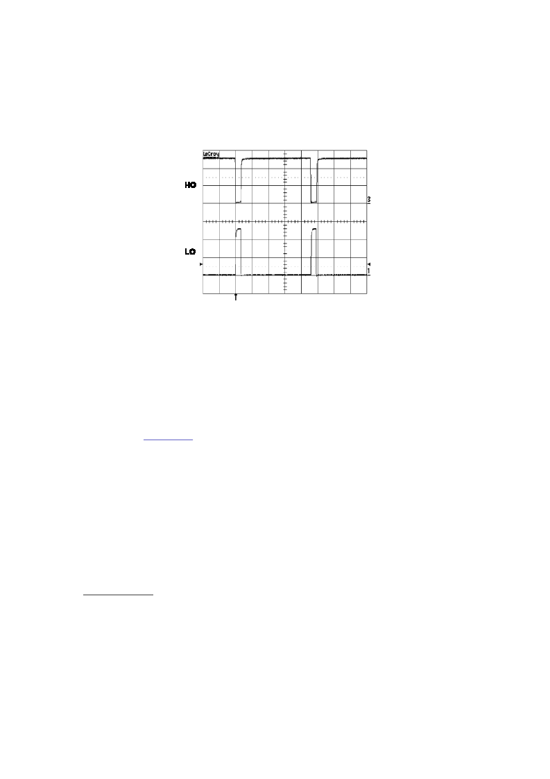
Fig. 21: Illustration of Watchdog Timer
The bootstrap capacitor value needs to be chosen so that it maintains sufficient charge for at least the
20 μs interval until the watchdog timer allows the capacitor to recharge. If the capacitor value is too
small, the charge will fully dissipate in less than 20 μs. The bootstrap capacitor should be at least 100
nF. A larger value within reason can be used if preferred.
The bootstrap diode should be a fast recovery, if not an ultrafast recovery component to maintain good
efficiency. Since the cathode of the bootstrap diode will be switching between COM and V
BUS
+ 14 V,
the reverse recovery time of this diode is of critical importance. For additional information concerning
the bootstrap components, refer to the Design Tip (DT 98-2),
“Bootstrap Component Selection For
Control ICs”
at
www.irf.com
under Design Support.
8.
Enable pin
The enable pin can be used for dimming and open-circuit protection. When the ENN pin is held low,
the chip remains in a fully functional state with no alterations to the operating environment. To disable
the control feedback and regulation, a voltage greater than V
ENTH
(approximately 2.5 V) needs to be
applied to the ENN pin. With the chip in a disabled state, HO output will remain low, where as the LO
output will remain high to prevent V
S
from floating, in addition to maintaining charge on the bootstrap
capacitor. The threshold for disabling the IRS254(0,1) has been set to 2.5 V to enhance immunity to
any externally generated noise, or application ground noise. This 2.5 V threshold also makes it ideal to
receive a drive signal from a local microcontroller.
Dimming mode
To achieve dimming, a signal with constant frequency and set duty cycle can be fed into the EN pin.
There is a direct linear relationship between the average load current and duty cycle. If the ratio is
50%, 50% of the maximum set light output will be realized. Likewise if the ratio is 30%, 70% of the
maximum set light output will be realized. A sufficiently high frequency of the dimming signal must
be chosen to avoid flashing or “strobe light” effect. A signal on the order of a few kHz should be
sufficient. For this evaluation board, a fully adjustable (0% to 100% duty cycle) PWM wave generator
has been designed but not included in the layout. The following design is a recommended enable
signal generator.
相關(guān)PDF資料 |
PDF描述 |
|---|---|
| IRS4426 | DUAL LOW SIDE DRIVER |
| IRS4428SPBF | DUAL LOW SIDE DRIVER |
| IRS4426PBF | DUAL LOW SIDE DRIVER |
| IRS4426S | DUAL LOW SIDE DRIVER |
| IRS4426SPBF | DUAL LOW SIDE DRIVER |
相關(guān)代理商/技術(shù)參數(shù) |
參數(shù)描述 |
|---|---|
| IRS25401 | 制造商:IRF 制造商全稱:International Rectifier 功能描述:LED BUCK REGULATOR CONTROL IC |
| IRS25401PBF | 功能描述:LED照明驅(qū)動(dòng)器 Hysteretic Buck LED Drvr RoHS:否 制造商:STMicroelectronics 輸入電壓:11.5 V to 23 V 工作頻率: 最大電源電流:1.7 mA 輸出電流: 最大工作溫度: 安裝風(fēng)格:SMD/SMT 封裝 / 箱體:SO-16N |
| IRS25401PBF | 制造商:International Rectifier 功能描述:IC LED DRVR DIP8 |
| IRS25401SPBF | 功能描述:LED照明驅(qū)動(dòng)器 200V HALF BRDG DRVR LED BUCK REGULATOR RoHS:否 制造商:STMicroelectronics 輸入電壓:11.5 V to 23 V 工作頻率: 最大電源電流:1.7 mA 輸出電流: 最大工作溫度: 安裝風(fēng)格:SMD/SMT 封裝 / 箱體:SO-16N |
| IRS25401STRPBF | 功能描述:LED照明驅(qū)動(dòng)器 Hysteretic Buck LED Drvr RoHS:否 制造商:STMicroelectronics 輸入電壓:11.5 V to 23 V 工作頻率: 最大電源電流:1.7 mA 輸出電流: 最大工作溫度: 安裝風(fēng)格:SMD/SMT 封裝 / 箱體:SO-16N |
發(fā)布緊急采購(gòu),3分鐘左右您將得到回復(fù)。