- 您現(xiàn)在的位置:買賣IC網(wǎng) > PDF目錄360993 > ISD1810 PDF資料下載
參數(shù)資料
| 型號: | ISD1810 |
| 文件頁數(shù): | 6/18頁 |
| 文件大小: | 464K |
| 代理商: | ISD1810 |
ISD1810 Product
3
ISD
SPEAKER OUTPUTS (SP+ , SP–)
The SP+ and SP– pins provide direct drive for loud-
speakers with impedances as low as 8
. A single
output may be used, but, for direct-drive loud-
speakers, the two opposite-polarity outputs pro-
vide an improvement in output power of up to four
times over a single-ended connection. Furthermore,
when SP+ and SP– are used, a speaker coupling
capacitor is not required. A single-ended connec-
tion will require an AC-coupling capacitor be-
tween the SP pin and the speaker.
The SP+ pin and the SP– pin are internally connected
through a 50 K
resistance. When not in playback
mode, they are floating.
EXTERNAL CLOCK (XCLK)
The external clock input for the ISD1810 devices
has an internal pull-down resistor. This pin is used
for test purposes only. Do not bond this pad.
RESISTOR CONTROLLED OSCILLATOR (ROSC)
The resistor controlled oscillator input enables the
user to vary the ISD1810 device record and play-
back duration. The resistor connected between
the ROSC pin and V
SS
(R2) determines the sample
frequency and the filter upper pass band for the
ISD1810 device. ISD recommends an ROSC resis-
tor value of 100 K
.
FEED THROUGH (FT)
Feed Through mode allows use of the speaker
drivers for external signals. The signal between the
MIC and MIC_REF pins will pass through the AGC,
the filter and the speaker drivers to the speaker
outputs SP+ and SP-. The input FT controls the feed
through mode. To operate this mode, the control
pins REC, PLAYE and PLAYL are held low at VSS. The
pin FT is held high to VCC. For normal operation of
record, play and power down, the FT pin is held at
VSS. The FT pin has a weak pull down to VSS.
SPECIFICATIONS
1.
Stresses above those listed may cause permanent
damage to the device. Exposure to the absolute
maximum ratings may affect device reliability.
Functional operation is not implied at these
conditions.
Table 2:
1.
2.
V
CC
= V
CCA
= V
CCD
.
V
SS
= V
SSA
= V
SSD
.
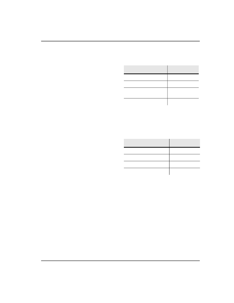
Table 1:
Absolute Maximum Ratings
1
Condition
Value
Junction temperature
150°C
Storage temperature range
–65°C to + 150°C
Voltage applied to any pad
(V
SS
– 0.3 V) to
(V
CC
+ 0.3 V)
V
CC
– V
SS
–0.3 V to + 7.0 V
Operating Conditions
Condition
Value
Operating temperature range
0°C to + 50°C
Play voltage (V
CC
)
(1)
+ 2.7V to + 4.5V
Ground voltage (V
SS
)
(2)
0 V
Record Supply voltage (V
CC
)
(1
+ 2.7V to 4.5V
相關PDF資料 |
PDF描述 |
|---|---|
| ISD1810SERIES | Single-Chip. Single-Message Voice Record/Playback Device |
| ISD25120PRODUCTS | |
| ISD25120S | (1.59 M) |
| ISD2532PRODUCTS | |
| ISD2540PRODUCTS | |
相關代理商/技術參數(shù) |
參數(shù)描述 |
|---|---|
| ISD1810P | 制造商:WINBOND 制造商全稱:Winbond 功能描述:Single-Chip, Single-Message Voice Record/Playback Device 8- to 16-Second Durations |
| ISD1810SERIES | 制造商:未知廠家 制造商全稱:未知廠家 功能描述:Single-Chip. Single-Message Voice Record/Playback Device |
| ISD1810SY | 功能描述:IC VOICE REC/PLAY 10SEC 28-SOIC RoHS:是 類別:集成電路 (IC) >> 接口 - 語音錄制和重放 系列:ISD1800 標準包裝:14 系列:- 接口:串行 濾波器通頻帶:1.7kHz 持續(xù)時間:8 ~ 32 秒 安裝類型:通孔 封裝/外殼:28-DIP(0.300",7.62mm) 供應商設備封裝:28-PDIP 其它名稱:90-21300+000 |
| ISD1810X | 制造商:WINBOND 制造商全稱:Winbond 功能描述:Single-Chip, Single-Message Voice Record/Playback Device 8- to 16-Second Durations |
| ISD1810X-H | 制造商:Nuvoton Technology Corp 功能描述:IC VOICE REC/PLAY 10SEC DIE |
發(fā)布緊急采購,3分鐘左右您將得到回復。