- 您現(xiàn)在的位置:買賣IC網(wǎng) > PDF目錄383143 > ISL6244HR (INTERSIL CORP) Multi-Phase PWM Controller PDF資料下載
參數(shù)資料
| 型號: | ISL6244HR |
| 廠商: | INTERSIL CORP |
| 元件分類: | 穩(wěn)壓器 |
| 英文描述: | Multi-Phase PWM Controller |
| 中文描述: | SWITCHING CONTROLLER, 1000 kHz SWITCHING FREQ-MAX, PQCC32 |
| 封裝: | 5 X 5 MM, PLASTIC, MO-220-VHHD, QFN-32 |
| 文件頁數(shù): | 11/25頁 |
| 文件大?。?/td> | 845K |
| 代理商: | ISL6244HR |
11
FN9106.3
December 28, 2004
PWM Operation
The timing of each converter leg is set by the number of
active channels. The default channel setting for the ISL6244
is four. One switching cycle is defined as the time between
PWM1 pulse termination signals. The pulse termination
signal is an internally generated clock signal which triggers
the falling edge of PWM1. The cycle time of the pulse
termination signal is the inverse of the switching frequency
set by the resistor between the FS pin and ground. Each
cycle begins when the clock signal commands the channel-1
PWM output to go low. The PWM1 transition signals the
channel-1 MOSFET driver to turn off the channel-1 upper
MOSFET and turn on the channel-1 synchronous MOSFET.
In the default channel configuration, the PWM2 pulse
terminates 1/4 of a cycle after PWM1. The PWM 3 output
follows another 1/4 of a cycle after PWM2. PWM4 terminates
another 1/4 of a cycle after PWM3.
If PWM3 is connected to VCC, then two channel operation is
selected and the PWM2 pulse terminates 1/2 of a cycle later.
Connecting PWM4 to VCC selects three channel operation and
the pulse-termination times are spaced in 1/3 cycle increments.
Once a PWM signal transitions low, it is held low for a
minimum of 1/4 cycle. This forced off time is required to
ensure an accurate current sample. Current sensing is
described in the next section. After the forced off time
expires, the PWM output is enabled. The PWM output state
is driven by the position of the error amplifier output signal,
V
COMP
, minus the current correction signal relative to the
sawtooth ramp as illustrated in Figure 1. When the modified
V
COMP
voltage crosses the sawtooth ramp, the PWM output
transitions high. The MOSFET driver detects the change in
state of the PWM signal and turns off the synchronous
MOSFET and turns on the upper MOSFET. The PWM signal
will remain high until the pulse termination signal marks the
beginning of the next cycle by triggering the PWM signal low.
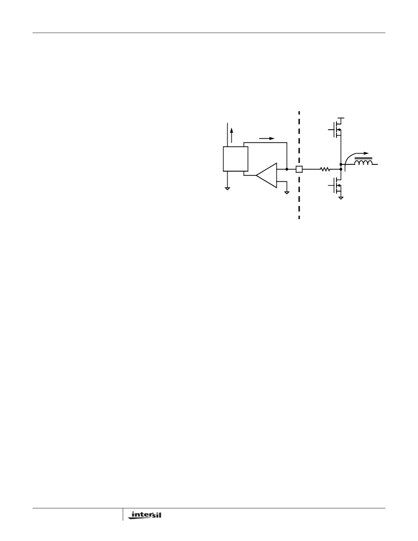
Current Sensing
During the forced off time following a PWM transition low, the
controller senses channel load current by sampling the
voltage across the lower MOSFET r
DS(ON)
, see Figure 15. A
ground-referenced amplifier, internal to the ISL6244,
connects to the PHASE node through a resistor, R
ISEN
. The
voltage across R
ISEN
is equivalent to the voltage drop
across the R
DS(ON)
of the lower MOSFET while it is
conducting. The resulting current into the ISEN pin is
proportional to the channel current, I
L
. The ISEN current is
then sampled and held after sufficient settling time every
switching cycle. The sampled current, I
n
, is used for
channel-current balance, load-line regulation and
overcurrent protection. From Figure 15, the following
equation for I
n
is derived
r
)
ISEN
where I
L
is the channel current.
If R
DS(ON)
sensing is not desired, an independent current-
sense resistor in series with the lower MOSFET source can
serve as a sense element. The circuitry shown in Figure 15
represents channel n of an N-channel converter. This
circuitry is repeated for each channel in the converter, but
may not be active depending upon the status of the PWM3
and PWM4 pins as described in the previous section.
Channel-Current Balance
The sampled current, I
n
, from each active channel is used to
gauge both overall load current and the relative channel
current carried in each leg of the converter. The individual
sample currents are summed and divided by the number of
active channels. The resulting average current, I
AVG
,
provides a measure of the total load current demand on the
converter and the appropriate level of channel current. Using
Figures 15 and 16, the average current is defined as:
where N is the number of active channels and I
OUT
is the
total load current.
The average current is then subtracted from the individual
channel sample currents. The resulting error current, I
ER
, is
then filtered before it adjusts V
COMP
. The modified V
COMP
signal is compared to a sawtooth ramp signal and produces
a pulse width which corrects for any imbalance and drives
the error current toward zero. Figure 16 illustrates Intersil’s
patented current-balance method as implemented on
channel-1 of a multi-phase converter.
I
n
I
L
-R
=
(EQ. 3)
FIGURE 15. INTERNAL AND EXTERNAL CURRENT-SENSING
CIRCUITRY
I
n
ISEN
IL
(
)
rRISEN
=
-
+
ISEN(n)
R
ISEN
SAMPLE
&
HOLD
ISL6244 INTERNAL CIRCUIT
EXTERNAL CIRCUIT
V
IN
CHANNEL N
UPPER MOSFET
CHANNEL N
LOWER MOSFET
-
+
ILrDS ON
(
)
I
L
(EQ. 4)
I
AVG
I
--------------N
I
…
I
N
+
+
=
I
AVG
I
-----N
r
ISEN
)
-R
=
ISL6244
相關PDF資料 |
PDF描述 |
|---|---|
| ISL6244CR-T | Multi-Phase PWM Controller |
| ISL6251HRZ-T | Low Cost Multi-Chemistry Battery Charger Controller |
| ISL6251HAZ-T | Low Cost Multi-Chemistry Battery Charger Controller |
| ISL6251AHRZ-T | Low Cost Multi-Chemistry Battery Charger Controller |
| ISL6251 | Octal D-Type Transparent Latches With 3-State Outputs 20-TSSOP -40 to 85 |
相關代理商/技術參數(shù) |
參數(shù)描述 |
|---|---|
| ISL6244HR-T | 功能描述:IC REG CTRLR BUCK PWM 32-QFN RoHS:否 類別:集成電路 (IC) >> PMIC - 穩(wěn)壓器 - DC DC 切換控制器 系列:- 標準包裝:4,000 系列:- PWM 型:電壓模式 輸出數(shù):1 頻率 - 最大:1.5MHz 占空比:66.7% 電源電壓:4.75 V ~ 5.25 V 降壓:是 升壓:無 回掃:無 反相:無 倍增器:無 除法器:無 Cuk:無 隔離:無 工作溫度:-40°C ~ 85°C 封裝/外殼:40-VFQFN 裸露焊盤 包裝:帶卷 (TR) |
| ISL6244HRZ | 功能描述:電流型 PWM 控制器 VER OF ISL6244HR RoHS:否 制造商:Texas Instruments 開關頻率:27 KHz 上升時間: 下降時間: 工作電源電壓:6 V to 15 V 工作電源電流:1.5 mA 輸出端數(shù)量:1 最大工作溫度:+ 105 C 安裝風格:SMD/SMT 封裝 / 箱體:TSSOP-14 |
| ISL6244HRZ-T | 功能描述:電流型 PWM 控制器 VER OF ISL6244HR-T RoHS:否 制造商:Texas Instruments 開關頻率:27 KHz 上升時間: 下降時間: 工作電源電壓:6 V to 15 V 工作電源電流:1.5 mA 輸出端數(shù)量:1 最大工作溫度:+ 105 C 安裝風格:SMD/SMT 封裝 / 箱體:TSSOP-14 |
| ISL6246C WAF | 制造商:Intersil Corporation 功能描述: |
| ISL6247 6248 WAF | 制造商:Intersil Corporation 功能描述: |
發(fā)布緊急采購,3分鐘左右您將得到回復。