- 您現(xiàn)在的位置:買(mǎi)賣(mài)IC網(wǎng) > PDF目錄383145 > ISL6308CRZ-T (INTERSIL CORP) Quadruple 2-Input Exclusive-OR Gates 14-SOIC -40 to 85 PDF資料下載
參數(shù)資料
| 型號(hào): | ISL6308CRZ-T |
| 廠商: | INTERSIL CORP |
| 元件分類(lèi): | 穩(wěn)壓器 |
| 英文描述: | Quadruple 2-Input Exclusive-OR Gates 14-SOIC -40 to 85 |
| 中文描述: | SWITCHING CONTROLLER, 1500 kHz SWITCHING FREQ-MAX, PQCC40 |
| 封裝: | 6 X 6 MM, ROHS COMPLIANT, PLASTIC, MO-220VJJD-1, QFN-40 |
| 文件頁(yè)數(shù): | 17/27頁(yè) |
| 文件大小: | 765K |
| 代理商: | ISL6308CRZ-T |
第1頁(yè)第2頁(yè)第3頁(yè)第4頁(yè)第5頁(yè)第6頁(yè)第7頁(yè)第8頁(yè)第9頁(yè)第10頁(yè)第11頁(yè)第12頁(yè)第13頁(yè)第14頁(yè)第15頁(yè)第16頁(yè)當(dāng)前第17頁(yè)第18頁(yè)第19頁(yè)第20頁(yè)第21頁(yè)第22頁(yè)第23頁(yè)第24頁(yè)第25頁(yè)第26頁(yè)第27頁(yè)
17
FN9208.2
October 19, 2005
should have a gate threshold well below the maximum
voltage rating of the load/microprocessor.
In the event that during normal operation the PVCC or VCC
voltage falls back below the POR threshold, the pre-POR
overvoltage protection circuitry reactivates to protect from
any more pre-POR overvoltage events.
Open Sense Line Protection
In the case that either of the remote sense lines, VSEN or
GND, become open, the ISL6308 is designed to detect this
and shut down the controller. This event is detected by
monitoring the voltage on the IREF pin, which is a local
version of V
OUT
sensed at the outputs of the inductors.
If VSEN or RGND become opened, VDIFF falls, causing the
duty cycle to increase and the output voltage on IREF to
increase. If the voltage on IREF exceeds “VDIFF+1V”, the
controller will shut down. Once the voltage on IREF falls
below “VDIFF+1V”, the ISL6308 will restart at the beginning
of soft-start.
Overcurrent Protection
The ISL6308 detects overcurrent events by comparing the
droop voltage, V
DROOP
, to the OCSET voltage, V
OCSET
, as
shown in Figure 13. The droop voltage, set by the external
current sensing circuitry, is proportional to the output current
as shown in Equation 8. A constant 100
μ
A flows through
R
OCSET
, creating the OCSET voltage. When the droop
voltage exceeds the OCSET voltage, the overcurrent
protection circuitry activates. Since the droop voltage is
proportional to the output current, the overcurrent trip level,
I
MAX
, can be set by selecting the proper value for R
OCSET
,
as shown in Equation 13.
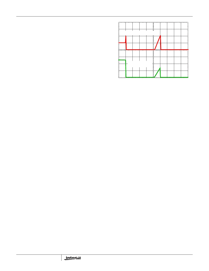
Once the output current exceeds the overcurrent trip level,
V
DROOP
will exceed V
OCSET
, and a comparator will trigger
the converter to begin overcurrent protection procedures. At
the beginning of overcurrent shutdown, the controller turns
off both upper and lower MOSFETs. The system remains in
this state for a period of 4096 switching cycles. If the
controller is still enabled at the end of this wait period, it will
attempt a soft-start (as shown in Figure 14). If the fault
remains, the trip-retry cycles will continue indefinitely until
either the controller is disabled or the fault is cleared. Note
that the energy delivered during trip-retry cycling is much
less than during full-load operation, so there is no thermal
hazard.
General Design Guide
This design guide is intended to provide a high-level
explanation of the steps necessary to create a multi-phase
power converter. It is assumed that the reader is familiar with
many of the basic skills and techniques referenced below. In
addition to this guide, Intersil provides complete reference
designs that include schematics, bills of materials, and
example board layouts for many applications.
Power Stages
The first step in designing a multi-phase converter is to
determine the number of phases. This determination
depends heavily on the cost analysis which in turn depends
on system constraints that differ from one design to the next.
Principally, the designer will be concerned with whether
components can be mounted on both sides of the circuit
board, whether through-hole components are permitted, the
total board space available for power-supply circuitry, and
the maximum amount of load current. Generally speaking,
the most economical solutions are those in which each
phase handles between 25 and 30A. All surface-mount
designs will tend toward the lower end of this current range.
If through-hole MOSFETs and inductors can be used, higher
per-phase currents are possible. In cases where board
space is the limiting constraint, current can be pushed as
high as 40A per phase, but these designs require heat sinks
and forced air to cool the MOSFETs, inductors and heat-
dissipating surfaces.
MOSFETs
The choice of MOSFETs depends on the current each
MOSFET will be required to conduct, the switching frequency,
the capability of the MOSFETs to dissipate heat, and the
availability and nature of heat sinking and air flow.
R
OCSET
I
R
DCR
S
---------------------------------------------------------
=
(EQ. 13)
0A
0V
OUTPUT CURRENT
FIGURE 14. OVERCURRENT BEHAVIOR IN HICCUP MODE
OUTPUT VOLTAGE
ISL6308
相關(guān)PDF資料 |
PDF描述 |
|---|---|
| ISL6308IRZ-T | Three-Phase Buck PWM Controller with High Current Integrated MOSFET Drivers |
| ISL6315 | Two-Phase Multiphase Buck PWM Controller with Integrated MOSFET Drivers(帶集成MOSFET驅(qū)動(dòng)器的雙相降壓PWM控制器) |
| ISL6316 | Quadruple 2-Input Exclusive-OR Gates 14-SOIC -40 to 85 |
| ISL6316IRZ | MINIATURE TOGGLE SWITCH |
| ISL6316CRZ | Enhanced 4-Phase PWM Controller with 6-Bit VID Code Capable of Precision RDS(ON) or DCR Differential Current Sensing for VR10 Application |
相關(guān)代理商/技術(shù)參數(shù) |
參數(shù)描述 |
|---|---|
| ISL6308CRZ-TR5374 | 制造商:Intersil Corporation 功能描述:ISL6308CRZ W/ 24HR BURN-IN - Tape and Reel 制造商:Intersil Corporation 功能描述:IC CTRLR PWM 3PHASE BUCK 40-QFN 制造商:Intersil 功能描述:ISL6308CRZ W/24HRU RN-IN |
| ISL6308CRZ-TR5453 | 制造商:Intersil Corporation 功能描述:STD. ISL6308CRZ-T W/GOLD BOND WIRE ONLY - Tape and Reel |
| ISL6308EVAL1Z | 制造商:Intersil Corporation 功能描述:ISL6308 EVALUATION BOARD 1 - ROHS COMPLIANT - QFN - Bulk |
| ISL6308IRZ | 功能描述:電壓模式 PWM 控制器 DAC-LESS MULTI-PHS PWM CNTRLR W/3-DRVRS RoHS:否 制造商:Texas Instruments 輸出端數(shù)量:1 拓?fù)浣Y(jié)構(gòu):Buck 輸出電壓:34 V 輸出電流: 開(kāi)關(guān)頻率: 工作電源電壓:4.5 V to 5.5 V 電源電流:600 uA 最大工作溫度:+ 125 C 最小工作溫度:- 40 C 封裝 / 箱體:WSON-8 封裝:Reel |
| ISL6308IRZ-T | 功能描述:電壓模式 PWM 控制器 DAC-LESS MULTI-PHS PWM CNTRLR W/3-DRVRS RoHS:否 制造商:Texas Instruments 輸出端數(shù)量:1 拓?fù)浣Y(jié)構(gòu):Buck 輸出電壓:34 V 輸出電流: 開(kāi)關(guān)頻率: 工作電源電壓:4.5 V to 5.5 V 電源電流:600 uA 最大工作溫度:+ 125 C 最小工作溫度:- 40 C 封裝 / 箱體:WSON-8 封裝:Reel |
發(fā)布緊急采購(gòu),3分鐘左右您將得到回復(fù)。