- 您現(xiàn)在的位置:買賣IC網(wǎng) > PDF目錄30714 > LA1781M AM/FM, AUDIO SINGLE CHIP RECEIVER, PQFP64 PDF資料下載
參數(shù)資料
| 型號: | LA1781M |
| 元件分類: | 接收器 |
| 英文描述: | AM/FM, AUDIO SINGLE CHIP RECEIVER, PQFP64 |
| 封裝: | 14 X 14 MM, QIP-64 |
| 文件頁數(shù): | 26/48頁 |
| 文件大?。?/td> | 508K |
| 代理商: | LA1781M |
第1頁第2頁第3頁第4頁第5頁第6頁第7頁第8頁第9頁第10頁第11頁第12頁第13頁第14頁第15頁第16頁第17頁第18頁第19頁第20頁第21頁第22頁第23頁第24頁第25頁當前第26頁第27頁第28頁第29頁第30頁第31頁第32頁第33頁第34頁第35頁第36頁第37頁第38頁第39頁第40頁第41頁第42頁第43頁第44頁第45頁第46頁第47頁第48頁

LA1781M
No.6038-32/48
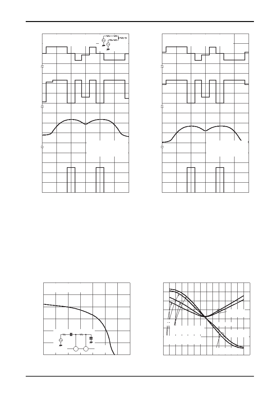
Notes on the quadrature input level
When a strong field is being received the quadrature signal input (pin 36) requires a 200mVrms input, and the
detection transformer and the damping resistor between pins 36 and 37 must be designed.
(We recommend the Sumida SA-208 transformer and a 10k
Ω resistor between pins 36 and 37.)
When the pin 36 input level falls below 160mVrms, the Hall detection circuit operates and the pin 33 mute drive
output voltage increases. Therefore, when pin 36 input is from 160 to under 200mV rms during strong field reception,
the muting circuit may or may not operate due to sample-to-sample variations between individual ICs.
Furthermore, the SD function may not operate, and the audio output level may be reduced. Incorrect operation due to
sample-to-sample variations and temperature characteristics can be prevented by keeping the pin 36 voltage at
200mVrms or higher.
36
37
SG
10.7MHz
LA1888M
75
Ω
75
Ω
+
0.022
μF
Pin 33 VMute -- QD Input Level
0
2
3
4
5
1
6
92
94
96
104
102
100
98
106
QD input level -- dB
μ
Vmute
-
V
THD
-
%
With pins 34 and 37 shorted.
With 5V applied to pin 24.
With a 10k
Ω resistor
between pins 36 and 37
THD 1kHz
75kHz dev
Δf -- kHz
Δf = 0 →
10.7kHz
With the resistorbetween
pins 36 and 37 open.
Voltage between pins 37 and 34
(referenced to the pin 37 voltage)
Fig. 29
SA208 + LA1781M IF Input Characteristics Fig. 30
0.2
--0.2
--0.4
--0.6
--0.8
0.4
0.6
0.8
1
2
3
4
0
--20
--40
--60
--80
20
40
60
80
100 120
--100
--120
f1
f2
ANT
IN
Unique Featuers of the LA1781M Hall Detection circuit (1)
0
4
6
--1
0
1
2
97.7
97.8
97.9
98.0
98.1
98.2
98.3
Frequency, fr -- MHz
Voltage
between
pins
37
and
34,
V
AFC
-
V
Pin
33,
V
Mute
-
V
0
4
6
2
Pin
24,
V
SM
-
V
0
4
6
8
2
Pin
26
(SD)
-
V
When the tuner is moved in 50kHz steps.
With a 51k
Ω resistor between pins 37 and 34.
With the SD sensitivity adjusted to be 20dB
μ.
f2 = 97.9MHz, 120dBμ
fm = 400Hz, 22.5kHz dev.
f1 = 98.1MHz, 120dBμ
fm = 1kHz, 22.5kHz dev.
Fig. 27
Unique Featuers of the LA1781M Hall Detection circuit (2)
0
4
6
--1
0
1
2
97.7
97.8
97.9
98.0
98.1
98.2
98.3
Frequency, fr -- MHz
Voltage
between
pins
37
and
34,
V
AFC
-
V
Pin
33,
V
Mute
-
V
0
4
6
2
Pin
24,
V
SM
-
V
0
4
6
8
2
Pin
26
(SD)
-
V
When the tuner is moved in 50kHz steps.
With a 51k
Ω resistor between pins 37 and 34.
With the SD sensitivity adjusted to be 20dB
μ.
f2 = 97.9MHz, 40dBμ
fm = 400Hz, 22.5kHz dev.
f1 = 98.1MHz, 40dBμ
fm = 1kHz, 22.5kHz dev.
Fig. 28
相關(guān)PDF資料 |
PDF描述 |
|---|---|
| LA1784M | AM/FM, AUDIO SINGLE CHIP RECEIVER, PQFP64 |
| LA1787NM | AM/FM, AUDIO SINGLE CHIP RECEIVER, PQFP64 |
| LA1787NM | AM/FM, AUDIO SINGLE CHIP RECEIVER, PQFP64 |
| LA1800 | AM/FM, AUDIO SINGLE CHIP RECEIVER, PDIP22 |
| LA1805 | AM/FM, AUDIO SINGLE CHIP RECEIVER, PDIP24 |
相關(guān)代理商/技術(shù)參數(shù) |
參數(shù)描述 |
|---|---|
| LA1781M_09 | 制造商:SANYO 制造商全稱:Sanyo Semicon Device 功能描述:For Car Radios Single-Chip Tuner IC |
| LA1781MA-MPB-E | 功能描述:調(diào)諧器 RoHS:否 制造商:NXP Semiconductors 功能: 噪聲系數(shù): 工作電源電壓: 最小工作溫度: 最大工作溫度: |
| LA1781MD-A-MPB-E | 制造商:ON Semiconductor 功能描述:ANALOG CAR RADIO TUNER - Trays |
| LA1781MD-B-MPB-E | 功能描述:調(diào)諧器 RoHS:否 制造商:NXP Semiconductors 功能: 噪聲系數(shù): 工作電源電壓: 最小工作溫度: 最大工作溫度: |
| LA1781ML-MPB-E | 功能描述:調(diào)諧器 RoHS:否 制造商:NXP Semiconductors 功能: 噪聲系數(shù): 工作電源電壓: 最小工作溫度: 最大工作溫度: |
發(fā)布緊急采購,3分鐘左右您將得到回復(fù)。