- 您現(xiàn)在的位置:買(mǎi)賣(mài)IC網(wǎng) > PDF目錄30714 > LA1781M AM/FM, AUDIO SINGLE CHIP RECEIVER, PQFP64 PDF資料下載
參數(shù)資料
| 型號(hào): | LA1781M |
| 元件分類(lèi): | 接收器 |
| 英文描述: | AM/FM, AUDIO SINGLE CHIP RECEIVER, PQFP64 |
| 封裝: | 14 X 14 MM, QIP-64 |
| 文件頁(yè)數(shù): | 44/48頁(yè) |
| 文件大小: | 508K |
| 代理商: | LA1781M |
第1頁(yè)第2頁(yè)第3頁(yè)第4頁(yè)第5頁(yè)第6頁(yè)第7頁(yè)第8頁(yè)第9頁(yè)第10頁(yè)第11頁(yè)第12頁(yè)第13頁(yè)第14頁(yè)第15頁(yè)第16頁(yè)第17頁(yè)第18頁(yè)第19頁(yè)第20頁(yè)第21頁(yè)第22頁(yè)第23頁(yè)第24頁(yè)第25頁(yè)第26頁(yè)第27頁(yè)第28頁(yè)第29頁(yè)第30頁(yè)第31頁(yè)第32頁(yè)第33頁(yè)第34頁(yè)第35頁(yè)第36頁(yè)第37頁(yè)第38頁(yè)第39頁(yè)第40頁(yè)第41頁(yè)第42頁(yè)第43頁(yè)當(dāng)前第44頁(yè)第45頁(yè)第46頁(yè)第47頁(yè)第48頁(yè)

LA1781M
No.6038-5/48
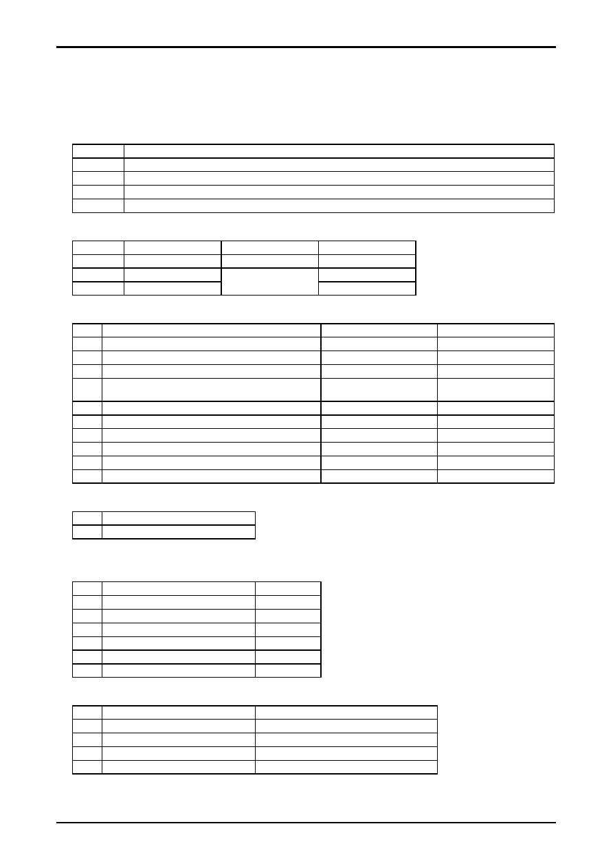
Operating Characteristics and Symbols Used in the Test Circuit Diagrams
(1) Switches (SW)
Switch on = 1, SW off = 0
There are two switches that use signal transfer.
1) SW2 : switches between the mixer input and the IF input.
2) SW4 : switches between noise canceler input and IF output + noise canceler input.
(2) Types of SG used
PG1 (AC1)
Used for noise canceler testing. A pulse generator and an AF oscillator are required.
AC2
Used for FM front end testing. Outputs an 83MHz signal.
AC3
Used for FM IF, noise canceler, and MPX testing. Outputs a 10.7MHz signal. Stereo modulation must be possible.
AC4
Used for AM testing. Outputs 1 MHz and 1.4MHz signals.
AC5
Used with the MRC. Can also be used for AF and OSC.
(3) Power supply
VCC
8V
VCC1
5V
SD, stereo, seek/stop
VCC2
0.1V/0.7V/2V/4V
Keyed AGC, Mute ATT
VCC3
0.1V/0.6V/2V
These levels must be
variable.
HCC, SNC, SASC (MRC)
(4) (a) Switches
Parameter
ON
OFF
SW1
AM/FM switching. The FE VCC is supplied to pin 62.
FM
AM
SW2
FM IF switching. Pin 51/FE output
FE IF OUT (A)
AC3 (B)
SW3
For conversion gain testing
Conversion gain measurement (A)
Other/purposes
SW4
For switching between noise canceler input and IF output + noise
canceler.
AC1 (A)
Other/purposes
SW5
High-speed SD
Other/purposes
SW6
SEEK/STOP (IF BUFF ON/OFF)
STOP
Seek (IF buffer output)
SW7
MUTE ATT 200k
Ω
MUTE 200k
Ω
OFF
SW8
MUTE ATT 30k
Ω
MUTE 30k
Ω
OFF
SW9
For pilot cancellation testing
When pilot cancellation is used
When pilot cancellation is not used
SW10
Mute off (pin 33)
MUTE OFF
MUTE ON
(b) Trimmers (variable resistors)
VR1
Separation adjustment
VR2
Pilot cancellation adjustment
(5) Test Points
(a) DC voltages
VD1
FM RF AGC voltage
Pin 2
VD2
AM/FM SD, AM Tweet, FM stereo indicator
Pin 26
VD3
AM/FM S-meter
Pin 24
VD4
MRC output
Pin 27
VD5
Mute drive output
Pin 33
VD6
AM antenna damping voltage
Pin 46
VD7
N.C. Gate time
Pin 8
(b) AC voltages
VA1
AM/FM OSC Buff
Pin 4
VA2
First IF output
Pin 53
→ CF → pin 51 load level (10.7MHz)
VA3
IF counter buffer
Pin 23 (10.7MHz/450kHz)
VA4
MPX OUT Left ch
Pin 15 (AF)
VA5
MPX OUT Right ch
Pin 16 (AF)
相關(guān)PDF資料 |
PDF描述 |
|---|---|
| LA1784M | AM/FM, AUDIO SINGLE CHIP RECEIVER, PQFP64 |
| LA1787NM | AM/FM, AUDIO SINGLE CHIP RECEIVER, PQFP64 |
| LA1787NM | AM/FM, AUDIO SINGLE CHIP RECEIVER, PQFP64 |
| LA1800 | AM/FM, AUDIO SINGLE CHIP RECEIVER, PDIP22 |
| LA1805 | AM/FM, AUDIO SINGLE CHIP RECEIVER, PDIP24 |
相關(guān)代理商/技術(shù)參數(shù) |
參數(shù)描述 |
|---|---|
| LA1781M_09 | 制造商:SANYO 制造商全稱(chēng):Sanyo Semicon Device 功能描述:For Car Radios Single-Chip Tuner IC |
| LA1781MA-MPB-E | 功能描述:調(diào)諧器 RoHS:否 制造商:NXP Semiconductors 功能: 噪聲系數(shù): 工作電源電壓: 最小工作溫度: 最大工作溫度: |
| LA1781MD-A-MPB-E | 制造商:ON Semiconductor 功能描述:ANALOG CAR RADIO TUNER - Trays |
| LA1781MD-B-MPB-E | 功能描述:調(diào)諧器 RoHS:否 制造商:NXP Semiconductors 功能: 噪聲系數(shù): 工作電源電壓: 最小工作溫度: 最大工作溫度: |
| LA1781ML-MPB-E | 功能描述:調(diào)諧器 RoHS:否 制造商:NXP Semiconductors 功能: 噪聲系數(shù): 工作電源電壓: 最小工作溫度: 最大工作溫度: |
發(fā)布緊急采購(gòu),3分鐘左右您將得到回復(fù)。