- 您現(xiàn)在的位置:買(mǎi)賣(mài)IC網(wǎng) > PDF目錄30719 > LA49101H 10 W, 1 CHANNEL, AUDIO AMPLIFIER, PDSO28 PDF資料下載
參數(shù)資料
| 型號(hào): | LA49101H |
| 元件分類(lèi): | 音頻/視頻放大 |
| 英文描述: | 10 W, 1 CHANNEL, AUDIO AMPLIFIER, PDSO28 |
| 封裝: | HSOP-28 |
| 文件頁(yè)數(shù): | 10/11頁(yè) |
| 文件大?。?/td> | 203K |
| 代理商: | LA49101H |

LA49101H
No. A1049-8/11
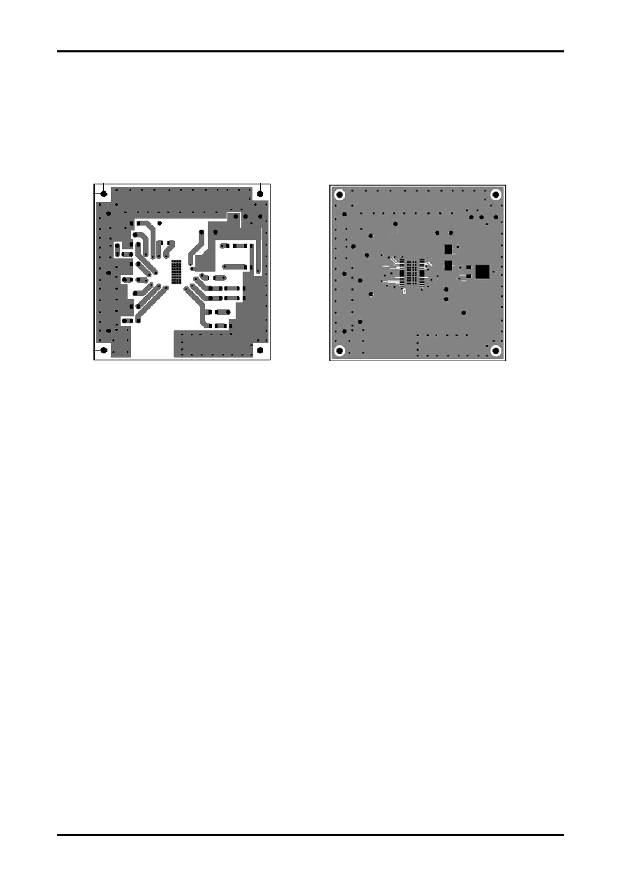
Basic specifications (LA49101H operation recommended substrate)
1) Four-layer substrate (2S2P)
Substrate size: 90mm × 90mm × 1.6tmm (glass epoxy)
Copper wiring density: L1=60% / L2=90% / L3=90% / L4=90% (LA49101H mounting surface)
2) Two-layer substrate (2S0P)
Substrate size: 90mm × 90mm × 1.6tmm (glass epoxy)
Copper wiring density: L1=60% / L2=90% (LA49101H mounting surface)
L1: Copper wiring pattern diagram
L4 (4-layer substrate), L2 (2-layer substrate):
Copper wiring pattern diagram
Cautions
1) Data for backside solder mounting corresponds to the value when the heat sink surface is wet for 80% or more.
2) Be sure to attempt derating set design with allowance.
Stresses to be derated include the voltage, current, junction temperature, power loss, as well as mechanical stresses
such as shock, impact, and tension.
Accordingly, design must be made to minimize these stresses as low or small as possible.
General derating guidelines are as follows:
(1) Maximum value of 80% or less for the voltage rating
(2) Maximum value of 80% or less for the current rating
(3) Maximum value of 80% or less for the temperature rating
3) Be sure to verify with the product after set design.
Check also the solder joint condition mainly of the heat sink and fin and verify the reliability of solder joint
Any void or deterioration in these solder joints may cause faulty heat conduction to the substrate, possibly resulting
in heat destruction of IC. Take due care to employ the solder of the composition optimizing use conditions, the
substrate land dimensions, mask, print conditions and superior in thermal fatigue resistance.
Cautions for Use
Lightening (power supply – output short-circuit) and ground fault (GND – output short-circuit) protection circuits are
incorporated, which are activated in case of abnormal connection. These circuits are activated while such abnormal
connection continues and automatically reset after canceling of abnormal condition.
The thermal protection circuit is incorporated and activated when the junction temperature (Tj) rises above about 160°C.
The output is controlled gradually to the attenuated condition.
When operation is made around the maximum ratings, even the slightest condition change may cause the parameter to
exceed these maximum ratings, resulting in damage. Take sufficient margin for the supply voltage and operate the
product within the range which never allows exceeding of the maximum ratings.
相關(guān)PDF資料 |
PDF描述 |
|---|---|
| LA4915 | 5 W, 2 CHANNEL, AUDIO AMPLIFIER, PDIP28 |
| LA4917H | 7 W, 2 CHANNEL, AUDIO AMPLIFIER, PDSO28 |
| LA4919N | 10 W, 2 CHANNEL, AUDIO AMPLIFIER, PDFM28 |
| LA5677M | 0.021 A SWITCHING CONTROLLER, 500 kHz SWITCHING FREQ-MAX, PDSO16 |
| LA5679T | 0.03 A SWITCHING CONTROLLER, 320 kHz SWITCHING FREQ-MAX, PDSO36 |
相關(guān)代理商/技術(shù)參數(shù) |
參數(shù)描述 |
|---|---|
| LA4917H | 制造商:SANYO 制造商全稱(chēng):Sanyo Semicon Device 功能描述:Monolithic Linear IC Audio Output for TV application High-Effciency Two-Channel 7W BTL Power Amplifier ICs |
| LA4919N | 制造商:SANYO 制造商全稱(chēng):Sanyo Semicon Device 功能描述:Monolithic Linear IC Two-Channel 10W BTL High-Efficiency TV Audio Output Power Amplifier |
| LA4B-M1C2LV-G | 制造商:IDEC CORPORATION 功能描述:Switch Push Button N.O./N.C. DPDT Flush Rectangular Button 0.1A 250VAC 250VDC Momentary Contact PC Pins Panel Mount/Through Hole |
| LA4B-M1C2LV-W | 制造商:IDEC CORPORATION 功能描述:Switch Push Button N.O./N.C. DPDT Flush Rectangular Button 0.1A 250VAC 250VDC Momentary Contact PC Pins Panel Mount/Through Hole |
| LA4CA00 | 制造商:TE Connectivity 功能描述: |
發(fā)布緊急采購(gòu),3分鐘左右您將得到回復(fù)。