- 您現(xiàn)在的位置:買賣IC網(wǎng) > PDF目錄30720 > LA71586M (SANYO SEMICONDUCTOR CO LTD) SPECIALTY CONSUMER CIRCUIT, PQFP100 PDF資料下載
參數(shù)資料
| 型號: | LA71586M |
| 廠商: | SANYO SEMICONDUCTOR CO LTD |
| 元件分類: | 消費家電 |
| 英文描述: | SPECIALTY CONSUMER CIRCUIT, PQFP100 |
| 封裝: | 14 X 20 MM, QIP-100 |
| 文件頁數(shù): | 49/50頁 |
| 文件大小: | 1782K |
| 代理商: | LA71586M |
第1頁第2頁第3頁第4頁第5頁第6頁第7頁第8頁第9頁第10頁第11頁第12頁第13頁第14頁第15頁第16頁第17頁第18頁第19頁第20頁第21頁第22頁第23頁第24頁第25頁第26頁第27頁第28頁第29頁第30頁第31頁第32頁第33頁第34頁第35頁第36頁第37頁第38頁第39頁第40頁第41頁第42頁第43頁第44頁第45頁第46頁第47頁第48頁當(dāng)前第49頁第50頁
LA71586M
No.A0223-8/50
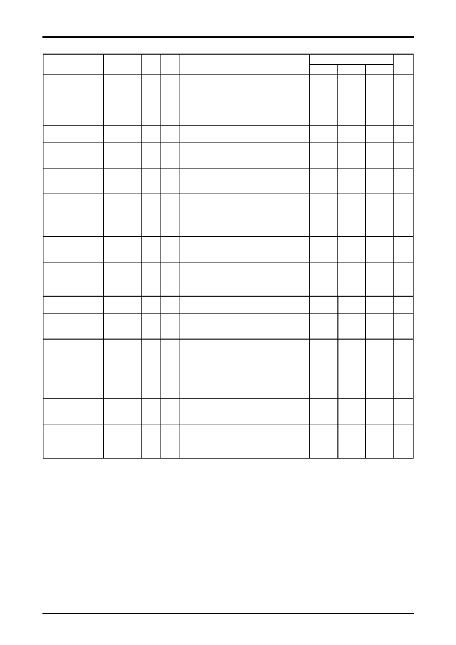
PB Mode Chroma
Ratings
Parameter
Symbol
In
Out
Conditions
min
typ
max
Unit
PB chroma video
output level
PAL MODE
PVop-29
T74A
T20A
T29
Input a chroma signal that is a lower frequency
converted chroma noise test signal (SP mode, burst
50mVp-p) to T74A.
Input a 4MHz 300mVp-p sine wave to T74A, and a
50% white signal to T20A.
Measure the burst level on T29.
490
580
670
mVp-p
PB chroma pin 72
output level
Vop-72
T74A
T20A
T72
Measure the burst level with the same conditions
as those for PVop-72.
280
mVp-p
PB ACC
characteristics (1)
ACCP1
T74A
T20A
T72
With the conditions used for PVop-29, increase the
input chroma level by +6dB, measure the burst level
on T72, and calculate the ratio with Vop-72.
+0.5
+0.8
dB
PB ACC
characteristics (2)
ACCP2
T74A
T20A
T72
With the conditions used for PVop-29, decrease the
input chroma level by -6dB, measure the burst level
on T72, and calculate the ratio with Vop-72.
-0.5
-0.2
dB
PB killer-on input level
VACK-P
T74A
T20A
T72
With the conditions used for Vop-29, the input chroma
level until output from T72 cease and measure the
input burst level at that point.
(Calculate the ratio with the standard input 50mVp-p
signal)
-25
dB
PB killer-on chroma
output level
VOACK-P
T74A
T20A
T29
Measure the T29 chroma output with a spectrum
analyzer in the killer state of the previous item.
Calculate its ratio with PVop-29.
-44
-40
dB
PB main converter
carrier leakage
CLP
T74A
T20A
T29
With the conditions used for PVop-29, measure the
T29 with a spectrum analyzer, and calculate the ratio
of the 4.43MHz component and the 5.06MHz carrier
leakage component.
-40
-33
dB
PB XO output level
PAL MODE
VXO-PP
T69A In PB mode, measure the output level on T69 with an
FET probe.
300
500
700
mVp-p
PB XO oscillator
frequency deviation
PAL MODE
fXOP
T69A In PB mode, let f be the measured frequency on T69.
fXOP = f-4433619 (Hz)
-9
0
+9
Hz
NTSC
→ PAL
conversion
V axis Burst level
VBNAP
T1A
T10A
T27
Input a chroma signal that is a lower frequency
converted chroma noise test signal (SP mode, burst
100mVp-p) to T1A.
Input a 4MHz 300mVp-p sine wave to T1A, and a
50% white signal to T10A.
Measure the T27-45
° Burst level, and take the ratio
with the PVOP-27.
-2
-1
0
dB
NTSC
→ PAL
conversion
Ratio of the Burst level
B-NAP
T1A
T10A
T27
With the same condition above, measure the Burst
level, and take the ratio with VBNAP.
-2
0
2
dB
PB Chroma 2nd
harmonic distortion
PTHD2
T1A
T10A
T27
With the conditions used for PVOP-27, measure the
T27 with a spectrum analyzer, and calculate the ratio
of the 4.43MHz component and the 8.86MHz
component.
-25
dB
相關(guān)PDF資料 |
PDF描述 |
|---|---|
| LA71598HM | SPECIALTY CONSUMER CIRCUIT, PQFP100 |
| LA71598HM | SPECIALTY CONSUMER CIRCUIT, PQFP100 |
| LA7160M | SPECIALTY CONSUMER CIRCUIT, PDSO16 |
| LA7161BM | SPECIALTY CONSUMER CIRCUIT, PDSO16 |
| LA7161BV | SPECIALTY CONSUMER CIRCUIT, PDSO16 |
相關(guān)代理商/技術(shù)參數(shù) |
參數(shù)描述 |
|---|---|
| LA7160M | 制造商:SANYO 制造商全稱:Sanyo Semicon Device 功能描述:VHF Band RF Modulator |
| LA7161BM | 制造商:SANYO 制造商全稱:Sanyo Semicon Device 功能描述:VHF Band RF Modulator (US3, 4ch, JPN1, 2ch,TWN13ch compatible) |
| LA7161BV | 制造商:SANYO 制造商全稱:Sanyo Semicon Device 功能描述:VHF Band RF Modulator (US3, 4ch, JPN1, 2ch,TWN13ch compatible) |
| LA7161NMTLM | 制造商:SANYO 功能描述:* |
| LA7161NV | 制造商:SANYO 制造商全稱:Sanyo Semicon Device 功能描述:VHF Band RF Modulator(SUPPORTS US 3,4CH, JPN 1,2CH, TWN 13CH) |
發(fā)布緊急采購,3分鐘左右您將得到回復(fù)。