- 您現(xiàn)在的位置:買賣IC網(wǎng) > PDF目錄369717 > LA7578 PDF資料下載
參數(shù)資料
| 型號(hào): | LA7578 |
| 文件頁(yè)數(shù): | 17/18頁(yè) |
| 文件大小: | 252K |
| 代理商: | LA7578 |
第1頁(yè)第2頁(yè)第3頁(yè)第4頁(yè)第5頁(yè)第6頁(yè)第7頁(yè)第8頁(yè)第9頁(yè)第10頁(yè)第11頁(yè)第12頁(yè)第13頁(yè)第14頁(yè)第15頁(yè)第16頁(yè)當(dāng)前第17頁(yè)第18頁(yè)
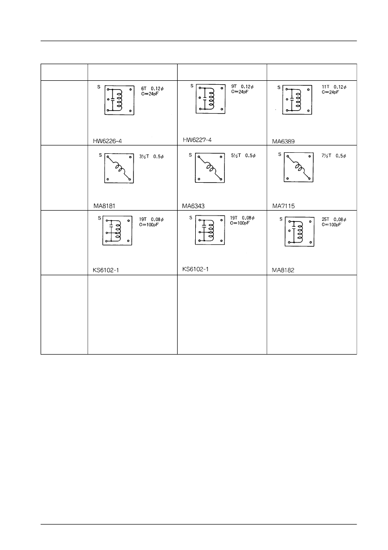
Coil Specifications
JAPAN
f = 58.75 MHz
US
f = 45.75 MHz
PAL
f = 38.9 MHz
VCO coil
T
1
AFT coil
T
2
SIF coil
T
4
SAW
Filter
(SANYO)
Picture
TSF1110M
TSF1110P
TSF1141P
M TYPE
P TYPE
P TYPE
Picture
TSF1203M
TSF1239P
TSF1233P
M TYPE
P TYPE
P TYPE
Picture
(MULTI)TSF5321
(BG) TSF5316U
(38M MULTI)
K TYPE
U TYPE
TSF5341U
U TYPE
( VCO tank circuit design considerations)
a.
VCO tank circuit with an internal capacitor
When power is supplied to the IC, the heat from the IC is propagated to the PCB, and then to the VCO tank. In this instance,
the legs of the tank coil substitute for a heat sink. Because the heat radiates from there, heat is not easily propagated to the
VCO tank’s internal capacitor, reducing the effect on VCO drift when the power is on.
Accordingly, it is desirable for the design to basically seek to cancel out the temperature characteristics through the L and C.
Basically, it is best to use an L with a core material that has small temperature characteristics, and also to use a capacitor
with small temperature characteristics.
VCO tank circuit with an external capacitor
In the case of an external chip capacitor, the heat from the IC is propagated to the PCB, and then to the external chip
capacitor. As a result, the chip capacitor is affected by the heat, and its capacitance changes. In this case, because the VCO
coil is relatively unaffected, the end result is that the alignment point of the VCO tank changes.
Accordingly, it is best to use an L with a core material that has small temperature characteristics, and also to use a capacitor
with small temperature characteristics.
b.
LA7578N
No.4037-17/18
相關(guān)PDF資料 |
PDF描述 |
|---|---|
| LA7640 | |
| LA7685 | |
| LA7802 | Analog IC |
| LA7900 | |
| LA7905 | |
相關(guān)代理商/技術(shù)參數(shù) |
參數(shù)描述 |
|---|---|
| LA7578N | 制造商:SANYO 制造商全稱:Sanyo Semicon Device 功能描述:IF Signal Processing (Super PLL-II VIF + SIF) Circuit for TVs and VCRs |
| LA7583 | 制造商:SANYO 制造商全稱:Sanyo Semicon Device 功能描述:IF Signal Processing Circuit (A2C PLL VIF + SIF) for TVs and VCRs |
| LA7590 | 制造商:未知廠家 制造商全稱:未知廠家 功能描述:Analog IC |
| LA7600 | 制造商:未知廠家 制造商全稱:未知廠家 功能描述: |
| LA7601 | 制造商:未知廠家 制造商全稱:未知廠家 功能描述:Consumer IC |
發(fā)布緊急采購(gòu),3分鐘左右您將得到回復(fù)。