- 您現(xiàn)在的位置:買賣IC網(wǎng) > PDF目錄43902 > LC016CL (LINEAGE POWER LLC) 2-OUTPUT 16 W DC-DC REG PWR SUPPLY MODULE PDF資料下載
參數(shù)資料
| 型號: | LC016CL |
| 廠商: | LINEAGE POWER LLC |
| 元件分類: | 電源模塊 |
| 英文描述: | 2-OUTPUT 16 W DC-DC REG PWR SUPPLY MODULE |
| 封裝: | MODULE-9 |
| 文件頁數(shù): | 3/16頁 |
| 文件大?。?/td> | 389K |
| 代理商: | LC016CL |

Advance Data Sheet
LC016 Dual-Output Series Power Modules:
April 2008
18 Vdc to 36 Vdc Inputs; 16 W
11
Lineage Power.
Thermal Considerations (continued)
Heat Transfer Without Heat Sinks (continued)
Note that the natural convection condition was mea-
sured at 0.05 ms–1 (10 ft./min.) to 0.1 ms–1 (20 ft./min.);
however, systems in which these power modules may
be used typically generate natural convection airflow
rates of 0.3 ms–1 (60 ft./min.) due to other heat dissipat-
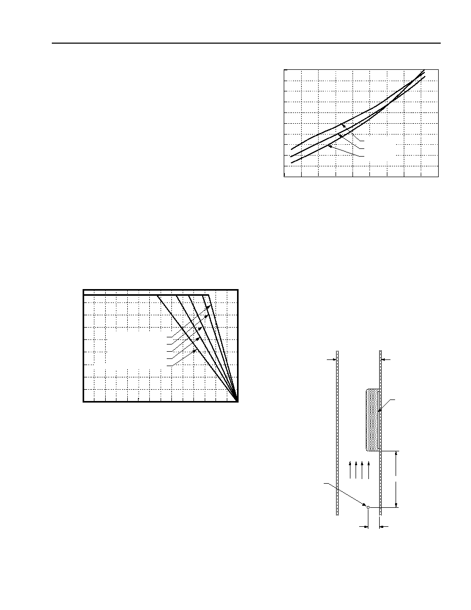
ing components in the system. Use of Figure 12 is
shown in the following example.
Example
What is the minimum airflow necessary for a LC016AJ
operating at high line, an output current of 0.8 A on
each output, and a maximum ambient temperature of
82 °C?
Solution:
Given: VI = 36 V, IO1 = IO2 = 0.8 A, TA = 82 °C
Determine Airflow (Figure 12): v = 0.5 ms–1
(100 ft./min.)
8-1282(C).a
Figure 12. Forced Convection Power Derating with
No Heat Sink; Either Orientation
8-1370(C)
Figure 13. LC016AJ Power Dissipation vs. Output
Current, TA = 25 °C
Module Derating
The derating curves in Figure 12 were obtained from
measurements obtained in an experimental apparatus
shown in Figure 14. Note that the module and the
printed-wiring board (PWB) that it is mounted on are
vertically oriented. The passage has a rectangular
cross section.
8-1126.a(C)
Note: Dimensions are in millimeters and (inches).
Figure 14. Experimental Test Setup
PO
WER
DISSIP
A
TION,
P
D
(W)
30
50
90
40
60
70
80
0.0
1.0
AMBIENT TEMPERATURE,
TA (C)
1.5
2.0
2.5
3.0
3.5
0.5
4.0
4.5
100
3.0 ms
-1 (600 ft/min.)
2.0 ms
-1 (400 ft/min.)
1.0 ms
-1 (200 ft/min.)
0.5 ms
-1(100 ft/min.)
NATURAL
CONVECTION
0.0
0.2
0.4
0.8
1.0
1.2
1.4
1.6
0.0
3.0
3.5
4.0
4.5
5.0
OUTPUT CURRENT
IO1,IO2 (A)
(I
O1
= IO2)
PO
WER
DISSIP
A
TION,
P
D
(W)
2.5
1.8
0.6
2.0
0.5
VIN = 36 V
VIN = 28 V
VIN = 18 V
1.0
1.5
AIR VELOCITY
AND AMBIENT
TEMPERATURE
MEASURED
BELOW THE
MODULE
AIRFLOW
12.7 (0.50)
FACING PWB
MODULE
76 (3.00)
PWB
相關(guān)PDF資料 |
PDF描述 |
|---|---|
| LC016BK | 2-OUTPUT 16 W DC-DC REG PWR SUPPLY MODULE |
| LC020A8 | DC-DC REG PWR SUPPLY MODULE |
| LC020B8 | DC-DC REG PWR SUPPLY MODULE |
| LC020F3 | DC-DC REG PWR SUPPLY MODULE |
| LC020F | DC-DC REG PWR SUPPLY MODULE |
相關(guān)代理商/技術(shù)參數(shù) |
參數(shù)描述 |
|---|---|
| LC016CL1 | 制造商:未知廠家 制造商全稱:未知廠家 功能描述:DC-to-DC Voltage Converter |
| LC016CL3 | 制造商:未知廠家 制造商全稱:未知廠家 功能描述:Analog IC |
| LC016CL7 | 制造商:未知廠家 制造商全稱:未知廠家 功能描述:Analog IC |
| LC016CL8 | 制造商:未知廠家 制造商全稱:未知廠家 功能描述:Analog IC |
| LC01-6T | 制造商:Semtech Corporation 功能描述:TVS DIODE, 1.5KW, 6V, SO-16W, Diode Type:(Not Available), Clamping Voltage Vc Ma |
發(fā)布緊急采購,3分鐘左右您將得到回復。