- 您現(xiàn)在的位置:買(mǎi)賣(mài)IC網(wǎng) > PDF目錄30743 > LM1253AAE/NA (NATIONAL SEMICONDUCTOR CORP) ON-SCREEN DISPLAY IC, PDIP28 PDF資料下載
參數(shù)資料
| 型號(hào): | LM1253AAE/NA |
| 廠(chǎng)商: | NATIONAL SEMICONDUCTOR CORP |
| 元件分類(lèi): | 畫(huà)面疊加 |
| 英文描述: | ON-SCREEN DISPLAY IC, PDIP28 |
| 封裝: | 0.600 INCH, PLASTIC, DIP-28 |
| 文件頁(yè)數(shù): | 56/61頁(yè) |
| 文件大小: | 1671K |
| 代理商: | LM1253AAE/NA |
第1頁(yè)第2頁(yè)第3頁(yè)第4頁(yè)第5頁(yè)第6頁(yè)第7頁(yè)第8頁(yè)第9頁(yè)第10頁(yè)第11頁(yè)第12頁(yè)第13頁(yè)第14頁(yè)第15頁(yè)第16頁(yè)第17頁(yè)第18頁(yè)第19頁(yè)第20頁(yè)第21頁(yè)第22頁(yè)第23頁(yè)第24頁(yè)第25頁(yè)第26頁(yè)第27頁(yè)第28頁(yè)第29頁(yè)第30頁(yè)第31頁(yè)第32頁(yè)第33頁(yè)第34頁(yè)第35頁(yè)第36頁(yè)第37頁(yè)第38頁(yè)第39頁(yè)第40頁(yè)第41頁(yè)第42頁(yè)第43頁(yè)第44頁(yè)第45頁(yè)第46頁(yè)第47頁(yè)第48頁(yè)第49頁(yè)第50頁(yè)第51頁(yè)第52頁(yè)第53頁(yè)第54頁(yè)第55頁(yè)當(dāng)前第56頁(yè)第57頁(yè)第58頁(yè)第59頁(yè)第60頁(yè)第61頁(yè)

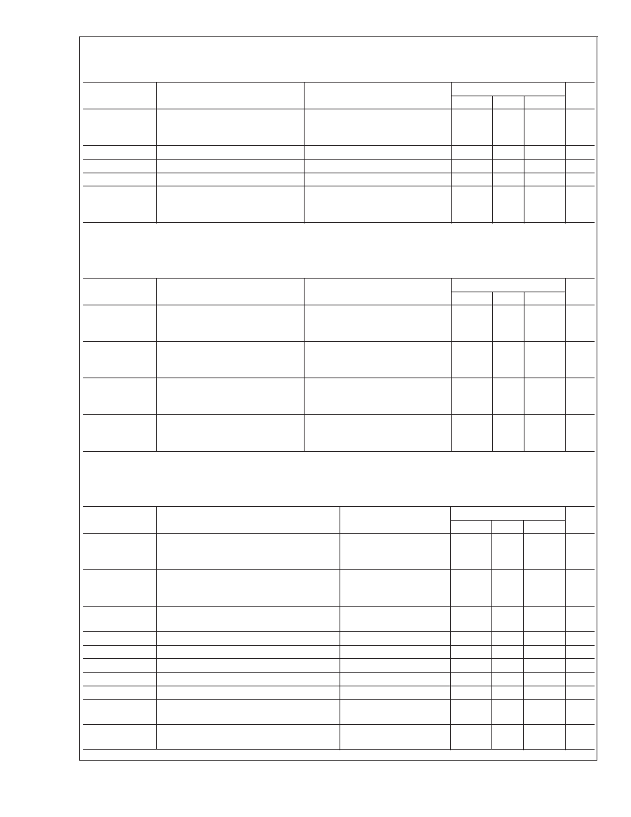
Brightness/Bias Signal Electrical Characteristics
(See
Figure 3 for Test Circuit, and Table 1 for Control Test Settings Chart)
Unless otherwise noted: V
CC = +5V, VIN = 0.7V, CL = 8 pF, Video Signal Output = 1 VPP,TA = 25C, VABL =VCC.
Symbol
Parameter
Conditions
LM1253A
Units
Min
Typ
Max
V
BLANK MAX
Maximum Blanking Level
Test Setting 1
V
REF
0.90
V
BLANK MIN
Minimum Blanking Level
Test Setting 4
V
REF
V
t
BLK r
Blanking Rise Time
Test Setting 1, 10% to 90%,
10
ns
t
BLK f
Blanking Fall Time
Test Setting 1, 90% to 10%,
10
ns
OS
BLK MAX
Maximum Rise or Fall Edge
Overshoot
Test Setting 1, 10% to 90% or
90% to 10%, Settling Time Must
be Less Than 50 ns
20
%
OSD Electrical Characteristics
(See
Figure 3 for Test Circuit)
Unless otherwise noted: V
CC = +5V, VIN = 0.7V, CL = 8 pF, Video Signal Output = 1 VPP,TA = 25C, VABL =VCC.
Symbol
Parameter
Conditions
LM1253A
Units
Min
Typ
Max
V
OSDHIGH MAX
Maximum OSD Level with OSD
Contrast 11
Palette Set at 111. OSD Contrast
Level 11, Test Setting 3
V
REF
+
0.95
V
OSDHIGH 10
Maximum OSD Level with OSD
Contrast 10
Palette Set at 111. OSD Contrast
Level 10, Test Setting 3
V
REF
+
0.77
V
OSDHIGH 01
Maximum OSD Level with OSD
Contrast 01
Palette Set at 111. OSD Contrast
Level 01, Test Setting 3
V
REF
+
0.59
V
OSDHIGH 00
Maximum OSD Level with OSD
Contrast 00
Palette Set at 111. OSD Contrast
Level 00, Test Setting 3
V
REF
+
0.41
V
External Interface Signals Electrical Characteristics
(See
Figure 3 for Test Circuit)
Unless otherwise noted: V
CC = +5V, VIN = 0.7V, CL = 8 pF, Video Signal Output = 1 VPP,TA = 25C, VABL =VCC.
Symbol
Parameter
Conditions
LM1253A
Units
Min
Typ
Max
I
INMAX
Maximum normal forward scan current at
lowest horizontal frequency that input can
withstand
150
A
V
HBLANK TRIG
Voltage on H Flyback (Pin 14) which will
Trigger an HBLANK Signal
100V H Flyback Signal
through a 100 k
Resistor
0.8
V
I
IN+MAX
Maximum flyback scan current at 125 kHz
that input can withstand
1.5
mA
t
min hflb
Minimum Flyback Width
1
s
t
H
Horizontal Period
20
125
kHz
t
PW CLAMP
Minimum Clamp Pulse Width
200
ns
V
CLAMP L MAX
Maximum Low Level Clamp Pulse Voltage
1
V
CLAMP H MIN
Minimum High Level Clamp Pulse Voltage
3
V
VBLANK HIGH
Minimum High Level of Vertical Blank
Output
V
VREF BLANK < 0.75V
V
REF
+1
V
VBLANK LOW
Maximum Low Level of Vertical Blank
Output
I
VBLANK OUT = 100 A
V
REF
1
V
LM1253A
www.national.com
6
相關(guān)PDF資料 |
PDF描述 |
|---|---|
| LM1267NA/NOPB | 3 CHANNEL, VIDEO PREAMPLIFIER, PDIP24 |
| LM1269NA/NOPB | 3 CHANNEL, VIDEO PREAMPLIFIER, PDIP24 |
| LM1276AAA/NA | 1 CHANNEL, VIDEO PREAMPLIFIER, PDIP28 |
| LM1279AN/NOPB | 3 CHANNEL, VIDEO AMPLIFIER, PDIP20 |
| LM1279N/NOPB | 1 CHANNEL, VIDEO AMPLIFIER, PDIP20 |
相關(guān)代理商/技術(shù)參數(shù) |
參數(shù)描述 |
|---|---|
| LM1253AN | 制造商:NSC 制造商全稱(chēng):National Semiconductor 功能描述:Monolithic Triple 180 MHz I2C CRT Pre-amp With Integrated Analog On Screen Display (OSD) Generator |
| LM-1256 | 制造商:ROHM 制造商全稱(chēng):Rohm 功能描述:16 x 16 matrix displays |
| LM-1256_1 | 制造商:ROHM 制造商全稱(chēng):Rohm 功能描述:16】16 matrix displays |
| LM-1256LB1 | 制造商:ROHM 制造商全稱(chēng):Rohm 功能描述:16】16 matrix displays |
| LM125AN | 制造商:NSC 制造商全稱(chēng):National Semiconductor 功能描述:VOLTAGE REGULATORS |
發(fā)布緊急采購(gòu),3分鐘左右您將得到回復(fù)。