- 您現(xiàn)在的位置:買賣IC網(wǎng) > PDF目錄30751 > LM4548VHX/NOPB (NATIONAL SEMICONDUCTOR CORP) SPECIALTY CONSUMER CIRCUIT, PQFP48 PDF資料下載
參數(shù)資料
| 型號: | LM4548VHX/NOPB |
| 廠商: | NATIONAL SEMICONDUCTOR CORP |
| 元件分類: | 消費家電 |
| 英文描述: | SPECIALTY CONSUMER CIRCUIT, PQFP48 |
| 封裝: | 7 X 7 MM, 1.40 MM HEIGHT, TQFP-48 |
| 文件頁數(shù): | 7/17頁 |
| 文件大小: | 328K |
| 代理商: | LM4548VHX/NOPB |

Application Information (Continued)
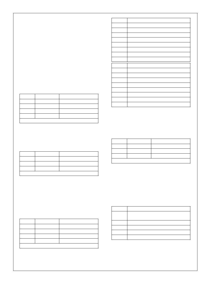
Register Descriptions
Reset Register (00h)
Writing any value to this register causes a register reset
which changes all of the registers back to their default val-
ues. If a read is performed on this register, the LM4548 will
return a value of 0D50h indicating that National 3D Sound is
implemented, 18bit data is supported for both the ADC’s and
DAC’s, and the volume control for True Line Level Out is
supported.
Master Volume Registers (02h, 04h, 06h)
These registers allow the output levels from LINE_OUT, LN-
LVL_OUT and MONO_OUT to be attenuated or muted.
There are 6-bits of volume control, plus one mute bit. It is a
5-bit volume range, where each step is nominally 1.5dB and
each output can be individually muted by either setting the
most significant bit (Mx5), and/or the mute bit (D15) to
″1.″
Mute
Mx5:Mx0
Function
0
00 0000
0dB attenuation
0
01 1111
46.5dB attenuation
0
1X XXXX
46.5dB attenuation
1
XX XXXX
mute
Default: 8000h
PC Beep Register (0Ah)
This register controls the level of the PC_BEEP input. The
PC_BEEP can be both attenuated and muted via register
0Ah. Step size is nominally 3dB. The signal present after the
attenuation and mute block is summed into both the left and
right channels.
Mute
PV3:0
Function
0
0000
0dB attenuation
0
1111
45dB attenuation
1
XXXX
mute
Default: 0000h
Mixer Input Volume Registers (Index 0Ch - 18h)
These registers set the input volume levels including mute.
Each volume control is 5 bit which provides from a range of
+12dB gain to 34.5dB attenuation in 1.5dB steps. For stereo
ports, the left and right levels can be independently set. Mut-
ing a given port is accomplished by setting the MSB to 1.
Setting the MSB to 1 for stereo ports mutes both the left and
right channel. Register 0Eh has an additional 20dB boost for
a microphone level input. This is enabled by setting bit 6 of
register 0Eh to 1.
Mute
Gx4:Gx0
Function
0
00000
+12dB gain
0
01000
0dB gain
0
11111
34.5dB attenuation
1
XXXXX
mute
Default: 8008h (mono regs.), 8808h (stereo regs.)
Record Select Register (1Ah)
This register independently controls the source for the right
and left channel which will be recorded by the stereo ADC.
The default value is 0000h which corresponds to Mic in.
SL2:SL0
Left Record Source
0
Mic
1
CDIn(L)
2
Video In (L)
3
Aux In (L)
4
Line In (L)
5
Stereo Mix (L)
6
Mono Mix (L)
7
Phone
SR2:SR0
Right Record Source
0
Mic
1
CDIn(R)
2
Video In (R)
3
Aux In (R)
4
Line In (R)
5
Stereo Mix (R)
6
Mono Mix (R)
7
Phone
Record (Input) Gain Register (1Ch)
This registers controls the Record (Input) Gain level for the
stereo input selected via the Record Select Control Register
(1Ah). The gain can be programmed from 0dB to +22.5dB in
1.5dB steps. The level for the left and right channel can be
individually controlled. The input can also be muted by set-
ting the MSB to 1.
Mute
Gx3:Gx0
Function
0
1111
22.5dB gain
0
0000
0dB gain
1
XXXX
mute
Default: 8000h
General Purpose Register (20h)
This register controls many miscellaneous functions imple-
mented on the LM4548. The miscellaneous functions include
POP which allows the PCM to bypass the National 3D
Sound circuitry, 3D which enables or disables the National
3D Sound circuitry, MIX which selects the MONO_OUT
source, MS which selects the microphone mux source and
LPBK which connects the output of the stereo ADC to input
of the stereo DAC. LPBK provides for a digital loopthru path
when enabled.
BIT
Function
POP
PCM out path and mute,0=pre 3D,1=
post 3D
3D
National 3D Sound on / off1=on
MIX
Mono output select0=Mix,1=Mic
MS
Mic select 0 = Mic1 1 = Mic2
LPBK
ADC/DAC loopback
Powerdown Control / Status Register (26h)
This read/write register is used to monitor subsystem readi-
ness and also to program the LM4548 powerdown states.
The lower half of this register is read only with a
″1″, indicat-
ing the subsection is ready. Writing to the lower 8 bits will
have no effect.
LM4548
www.national.com
15
相關(guān)PDF資料 |
PDF描述 |
|---|---|
| LM4549AVH/NOPB | SPECIALTY CONSUMER CIRCUIT, PQFP48 |
| LM4550VH/NOPB | SPECIALTY CONSUMER CIRCUIT, PQFP48 |
| LM4550VHX/NOPB | SPECIALTY CONSUMER CIRCUIT, PQFP48 |
| LM4560VJG | SPECIALTY CONSUMER CIRCUIT, PQFP100 |
| LM4651N/NOPB | 170 W, 1 CHANNEL, AUDIO AMPLIFIER, PDIP28 |
相關(guān)代理商/技術(shù)參數(shù) |
參數(shù)描述 |
|---|---|
| LM4549 | 制造商:NSC 制造商全稱:National Semiconductor 功能描述:AC ’97 Rev 2.1 Codec with Sample Rate Conversion and National 3D Sound |
| LM4549A | 制造商:NSC 制造商全稱:National Semiconductor 功能描述:AC ’97 Rev 2.1 Codec with Sample Rate Conversion and National 3D Sound |
| LM4549AVH | 制造商:Rochester Electronics LLC 功能描述:AC97 REV2.1 CODEC - Bulk 制造商:OC White Company 功能描述:Audio Codec 2ADC / 2DAC 18-Bit 48-Pin LQFP Tray |
| LM4549AVH WAF | 制造商:Texas Instruments 功能描述: |
| LM4549AVH/NOPB | 制造商:Texas Instruments 功能描述:Audio Codec 2ADC / 2DAC 18-Bit 48-Pin LQFP Tray |
發(fā)布緊急采購,3分鐘左右您將得到回復(fù)。