- 您現(xiàn)在的位置:買賣IC網(wǎng) > PDF目錄30751 > LM4801MH/NOPB (NATIONAL SEMICONDUCTOR CORP) 1.5 W, 2 CHANNEL, AUDIO AMPLIFIER, PDSO28 PDF資料下載
參數(shù)資料
| 型號: | LM4801MH/NOPB |
| 廠商: | NATIONAL SEMICONDUCTOR CORP |
| 元件分類: | 音頻/視頻放大 |
| 英文描述: | 1.5 W, 2 CHANNEL, AUDIO AMPLIFIER, PDSO28 |
| 封裝: | 4.40 MM, TSSOP-28 |
| 文件頁數(shù): | 15/20頁 |
| 文件大小: | 725K |
| 代理商: | LM4801MH/NOPB |

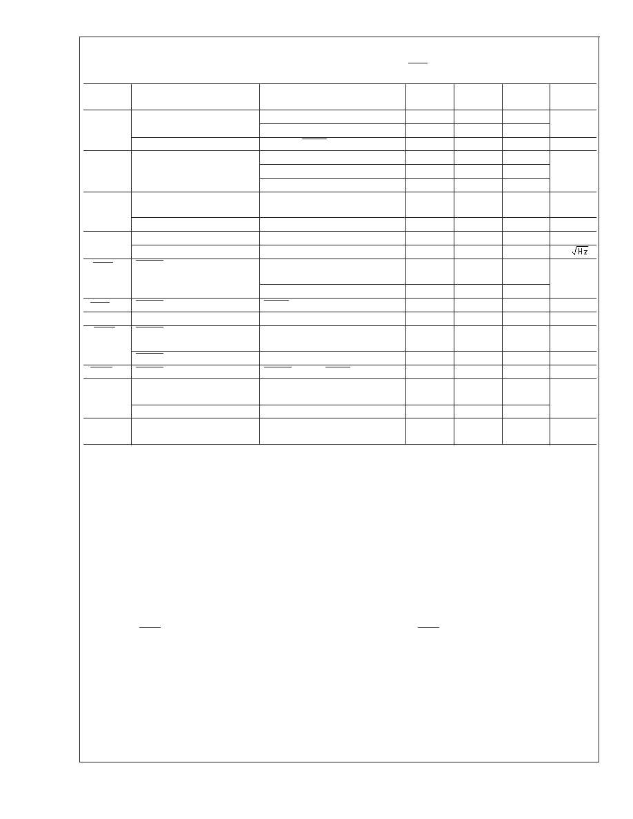
LDO Electrical Characteristics (Continued)
Unless otherwise specified, all limits guaranteed for V
T
J = 25C. Boldface limits apply for the operating temperature extremes: 40C and 85C.
Symbol
Parameter
Conditions
Min
Typ
Max
Units
I
Q
Supply Current
I
OUT = 0mA
90
270
A
I
OUT = 300mA
225
Shutdown Supply Current
V
O = 0V, SHDN = GND
0.001
1
A
V
DO
Dropout Voltage
I
OUT = 1mA
0.4
mV
I
OUT = 200mA
80
220
I
OUT = 300mA
120
V
O
Line Regulation
I
OUT = 1mA, (VO + 0.5V)
≤ V
I
≤ 6V
-0.1
0.01
0.1
%/V
Load Regulation
100A
≤ I
OUT
≤ 300mA
0.002
%/mA
e
n
Output Voltage Noise
I
OUT = 10mA, 10Hz
≤ f ≤ 100kHz
37
V
RMS
Output Voltage Noise Density
10Hz
≤ f ≤ 100kHz, C
OUT = 10F
190
nV/
V
SHDN
SHDN Input Threshold
V
IH,(VO + 0.5V)
≤ V
I
≤ 6V
2
V
IL,(VO + 0.5V)
≤ V
I
≤ 6V
0.4
I
SHDN
SHDN Input Bias Current
SHDN = GND or IN
0.1
100
nA
I
SET
SET Input Leakage
SET = 1.3V
0.1
2.5
nA
V
FAULT
FAULTDetection Voltage
V
O
≥ 2.5V, I
OUT = 200mA (Note
12)
120
280
mV
FAULT Output Low Voltage
I
SINK = 2mA
0.115
0.25
V
I
FAULT
FAULT Off-Leakage Current
FAULT = 3.6V, SHDN = 0V
0.1
100
nA
T
SD
Thermal Shutdown
Temperature
160
C
Thermal Shutdown Hysteresis
10
T
ON
Start-Up Time
C
OUT = 10F, VO at 90% of Final
Value
120
s
Note 1: Absolute Maximum Ratings indicate limits beyond which damage to the device may occur. Operating Ratings indicate conditions for which the device is
functional, but do not guarantee specific performance limits. Electrical Characteristics state DC and AC electrical specifications under particular test conditions which
guarantee specific performance limits. This assumes that the device is within the Operating Ratings. Specifications are not guaranteed for parameters where no limit
is given, however, the typical value is a good indication of device performance.
Note 2: The maximum power dissipation is dictated by TJMAX, θJA, and the ambient temperature TA and must be derated at elevated temperatures. The maximum
allowable power dissipation is PDMAX =(TJMAX TA)/θJA. For the LM4801, TJMAX = 150C. The θJAfor the LM4801 in the 28-pin MXA28A package, when board
mounted and its DAP is soldered to a 2in2 copper heatsink plane, is 41C/W.
Note 3: Human body model, 100pF discharged through a 1.5k
resistor.
Note 4: Machine model, 220pF–240pF discharged through all pins.
Note 5: All voltages are measured with respect to the ground (GND) pins unless otherwise specified.
Note 6: Typicals are measured at 25C and represent the parametric norm.
Note 7: Datasheet min/max specification limits are guaranteed by design, test, or statistical analysis.
Note 8: The quiescent power supply current depends on the offset voltage when a practical load is connected to the amplifier.
Note 9: Output power is measured at the device terminals.
Note 10: Condition does not apply to input voltages below 2.5V since this is the minimum input operating voltage.
Note 11: Dropout voltage is measured by reducing VIN until VO drops 100mV from its nominal value at VIN -VO = 0.5V. Dropout Voltage does not apply to the 1.8
version.
Note 12: The FAULT detection voltage is specified for the input to output voltage differential at which the FAULT pin goes active low.
LM4801
www.national.com
4
相關(guān)PDF資料 |
PDF描述 |
|---|---|
| LM4808MDC | 0.15 W, 2 CHANNEL, AUDIO AMPLIFIER, UUC |
| LM4808MWC | 0.15 W, 2 CHANNEL, AUDIO AMPLIFIER, UUC |
| LM4808LD/NOPB | 0.15 W, 2 CHANNEL, AUDIO AMPLIFIER, DSO8 |
| LM4808LDX/NOPB | 0.15 W, 2 CHANNEL, AUDIO AMPLIFIER, DSO8 |
| LM4809MDC | 0.105 W, 2 CHANNEL, AUDIO AMPLIFIER, UUC |
相關(guān)代理商/技術(shù)參數(shù) |
參數(shù)描述 |
|---|---|
| LM480261 | 制造商:SHARP 制造商全稱:Sharp Electrionic Components 功能描述:Medium Size Graphic Type LCD Module |
| LM4802B | 制造商:NSC 制造商全稱:National Semiconductor 功能描述:Audio Power Amplifier with Boost Converter to Drive Ceramic Speakers |
| LM4802BLQ | 功能描述:音頻放大器 RoHS:否 制造商:STMicroelectronics 產(chǎn)品:General Purpose Audio Amplifiers 輸出類型:Digital 輸出功率: THD + 噪聲: 工作電源電壓:3.3 V 電源電流: 最大功率耗散: 最大工作溫度: 安裝風格:SMD/SMT 封裝 / 箱體:TQFP-64 封裝:Reel |
| LM4802BLQ/NOPB | 功能描述:音頻放大器 RoHS:否 制造商:STMicroelectronics 產(chǎn)品:General Purpose Audio Amplifiers 輸出類型:Digital 輸出功率: THD + 噪聲: 工作電源電壓:3.3 V 電源電流: 最大功率耗散: 最大工作溫度: 安裝風格:SMD/SMT 封裝 / 箱體:TQFP-64 封裝:Reel |
| LM4802BLQBD | 功能描述:音頻 IC 開發(fā)工具 LM4802BLQ EVAL BOARD RoHS:否 制造商:Texas Instruments 產(chǎn)品:Evaluation Kits 類型:Audio Amplifiers 工具用于評估:TAS5614L 工作電源電壓:12 V to 38 V |
發(fā)布緊急采購,3分鐘左右您將得到回復(fù)。