- 您現(xiàn)在的位置:買賣IC網(wǎng) > PDF目錄361035 > LM9811 (National Semiconductor Corporation) 10-Bit Greyscale/30-Bit Color Linear CCD Sensor Processor PDF資料下載
參數(shù)資料
| 型號: | LM9811 |
| 廠商: | National Semiconductor Corporation |
| 英文描述: | 10-Bit Greyscale/30-Bit Color Linear CCD Sensor Processor |
| 中文描述: | 10位Greyscale/30-Bit彩色線陣CCD傳感器處理器 |
| 文件頁數(shù): | 3/36頁 |
| 文件大?。?/td> | 605K |
| 代理商: | LM9811 |
第1頁第2頁當前第3頁第4頁第5頁第6頁第7頁第8頁第9頁第10頁第11頁第12頁第13頁第14頁第15頁第16頁第17頁第18頁第19頁第20頁第21頁第22頁第23頁第24頁第25頁第26頁第27頁第28頁第29頁第30頁第31頁第32頁第33頁第34頁第35頁第36頁
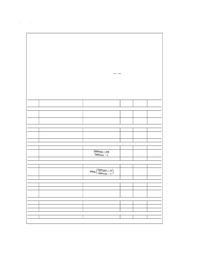
Absolute Maximum Ratings
(Notes 1, 2)
Positive Supply Voltage (V
+
= V
A
= V
D
= V
D(I/O
)
with Respect to
GND = AGND = DGND = DGND
(I/O)
Voltage on any Input or Output Pin
Input Current at any Pin (Note 3)
Package Input Current (Note 3)
Package Dissipation at T
A
= 25C
ESD Susceptibility (Note 5)
Human Body Model
Soldering Information (Note 6)
Infrared, 10 seconds
LM9811CCV
LM9811CCVF
Storage Temperature
Electrical Characteristics
The following specifications apply for AGND = DGND = DGND(I/O) = 0V, V
= V
= +5.0V
, V
= +5.0 or +3.0V
,
REF IN = +1.225V
DC
, f
MCLK
= 20MHz, R
= 25
. All LSB units are ADC LSBs unless otherwise specified.
Boldface limits
apply for T
A
= T
J
= T
MIN
to T
MAX
; all other limits T
A
= T
J
= 25C. (Note 8)
Symbol
Parameter
6.5V
0.3V to V
+
+0.3V
±
25 mA
±
50 mA
(Note 4)
2000V
300C
220C
65C to +150C
Operating Ratings
(Notes 1, 2)
Operating Temperature
Range
LM9811CCV, LM9811CCVF
V
A
Supply Voltage
V
D
Supply Voltage
V
D(I/O)
Supply Voltage
|V
A
–V
D
|
V
A
–V
D(I/O)
OS, REF IN Voltage Range
CD0–CD7, MCLK, SYNC,
SDI, SCLK, CS, RD,
Voltage Range
T
MIN
≤
T
A
≤
T
MAX
0C
≤
T
A
≤
+70C
+4.75V to +5.25V
+4.75V to +5.25V
+2.7V to +5.25V
≤
100 mV
≥
100 mV
0.05V to V
A
+ 0.05V
0.05V to V
D(I/O)
+ 0.05V
Conditions
Typical
(Note 9)
Limits
(Note 10)
Units
(Limits)
CCD SOURCE REQUIREMENTS FOR FULL SPECIFIED ACCURACY AND DYNAMIC RANGE
(Note 11)
V
WHITE
Maximum Peak CCD Differential
Signal Range
V
RFT
Maximum CCD Reset FeedThrough
Amplitude
ADC CHARACTERISTICS
(Note 16)
Resolution with No Missing Codes
VGA Gain = 0 dB
VGA Gain = 9 dB
1.1
0.4
V (min)
V (min)
2
V (min)
f
MCLK
= 12MHz
9
Bits (min)
LSB (max)
LSB (min)
LSB (max)
ILE
Integral Linearity Error (Note 12)
f
MCLK
= 12MHz
+4.0
3.0
+2.0
DNL
PGA CHARACTERISTICS
Monotonicity
Differential Non-Linearity
f
MCLK
= 12MHz
8
Bits (min)
PGA Adjustment Range
2.95
2.8
V/V (min)
Gain Error at any Gain (Note 14)
VGA CHARACTERISTICS
Monotonicity
1.4
% (max)
4
Bits (min)
VGA Adjustment Range
8.95
8.5
dB (min)
Gain Error at any Gain (Note 15)
OFFSET TRIM CHARACTERISTICS
Offset DAC LSB Size
Offset DAC DNL
±
0.15
dB (max)
In Units of ADC LSBs
In Units of Offset DAC LSBs
1.7
±
0.25
LSB
LSB
±
0.9
6.4
10.0
Offset Add Magnitude
In Units of ADC LSBs
8
LSB (min)
LSB (max)
SYSTEM CHARACTERISTICS
Full Channel Gain Error
Pre-PGA Offset Error (In ADC LSBs)
Post-PGA Offset Error (In ADC LSBs)
REFERENCE AND ANALOG INPUT CHARACTERSTICS
(Note 7)
OS Input Capacitance
VGA Gain = 1, PGA Gain = 1
VGA Gain = 1, Offset DAC = 0
Offset Add = 0
±
0.6
±
4
±
4
±
3.0
% (max)
LSB
LSB
5
pF
www.national.com
3
相關PDF資料 |
PDF描述 |
|---|---|
| LM9811CCV | 10-Bit Greyscale/30-Bit Color Linear CCD Sensor Processor |
| LM9831CCVJD | LM9831 42-Bit Color, 1200dpi USB Image Scanner |
| LM9831 | LM9831 42-Bit Color, 1200dpi USB Image Scanner |
| LM9831CCVJDX | LM9831 42-Bit Color, 1200dpi USB Image Scanner |
| LM9832CCVJD | LM9832 42-Bit Color, 1200dpi USB Image Scanner |
相關代理商/技術參數(shù) |
參數(shù)描述 |
|---|---|
| LM9811CCV | 制造商:NSC 制造商全稱:National Semiconductor 功能描述:10-Bit Greyscale/30-Bit Color Linear CCD Sensor Processor |
| LM9811CCVF | 制造商:NSC 制造商全稱:National Semiconductor 功能描述:10-Bit Greyscale/30-Bit Color Linear CCD Sensor Processor |
| LM9812 | 制造商:NSC 制造商全稱:National Semiconductor 功能描述:LM9812 30-Bit Color Linear CCD Sensor Processor |
| LM9812CCV | 制造商:NSC 制造商全稱:National Semiconductor 功能描述:LM9812 30-Bit Color Linear CCD Sensor Processor |
| LM981-SC36 | 功能描述:基本/快動開關 Foot Switch RoHS:否 制造商:Omron Electronics 觸點形式:SPDT 執(zhí)行器:Lever 電流額定值:5 A 電壓額定值 AC:250 V 電壓額定值 DC:30 V 功率額定值: 工作力:120 g IP 等級:IP 67 NEMA 額定值: 端接類型:Wire 安裝:Panel |
發(fā)布緊急采購,3分鐘左右您將得到回復。