- 您現(xiàn)在的位置:買賣IC網(wǎng) > PDF目錄377661 > LRZ2512R000 (TT Electronics / Welwyn) High Current Jumper Chip PDF資料下載
參數(shù)資料
| 型號: | LRZ2512R000 |
| 廠商: | TT Electronics / Welwyn |
| 英文描述: | High Current Jumper Chip |
| 中文描述: | 高電流跳線芯片 |
| 文件頁數(shù): | 2/3頁 |
| 文件大小: | 273K |
| 代理商: | LRZ2512R000 |
High Current Jumper Chip
LRZ Series
Welwyn Components Limited
Bedlington, Northumberland NE22 7AA, UK
Telephone: +44 (0) 1670 822181 · Facsimile: +44 (0) 1670 829465 · Email: info@welwyn-tt.com · Website: www.welwyn-tt.com
Issue B · 02.05
Application Notes
Conventional thick film “zero-Ohm” jumper chips typically
have up to 50m
resistance values and 1 to 2A current
ratings. LRZ jumper chips offer a solution for currents over an
order of magnitude greater by combining lower resistance
values with better thermal conductivity.
Care should be taken when designing the associated printed
circuit board tracks to ensure that they can carry the required
current without excessive heating, for example by using
multiple layers thermally linked with many vias. Any
temperature rise caused by power dissipated in the PCB tracks
themselves should be allowed for when calculating the
ambient temperature in order to determine whether power
de-rating should be applied. The minimum recommended pad
and trace areas close to the resistor stated under Electrical
Data should be provided at each terminal. For multi-layer
PCB’s, this minimum area requirement should be met by
surface layers rather than buried layers. The actual solder pad
area follows the normal design rules for chip resistors.
LRZ jumper chips themselves can operate at a maximum
temperature of 150C (see performance above). For
conventionally soldered jumper chips, the joint temperature
should not exceed 110C. This condition is met when the
stated current levels at 70C are used.
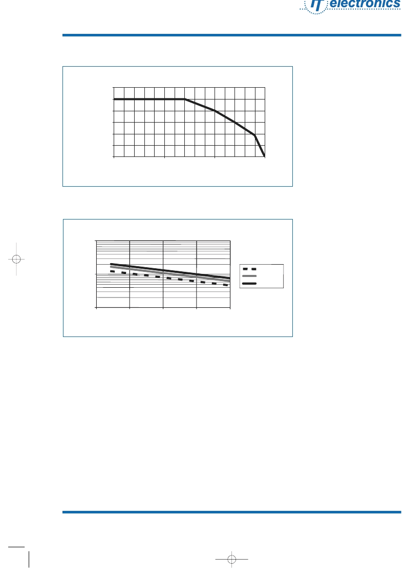
100%
80%
120%
60%
40%
20%
0%
0
50
100
150
Derating Characteristic
P
Ambient Temperature (C)
1000
10
0.1
1
10
100
1000
Pulse Duration (ms)
P
100
Continuous Pulse Performance
LRZ1206
LRZ2010
LRZ2512
Temperature Derating
Pulse Performance
Welwyn Components
相關(guān)PDF資料 |
PDF描述 |
|---|---|
| LS-401 | LOW NOISE LOW DRIFT MONOLITHIC DUAL N CHANNEL JFET |
| LS-402 | LOW NOISE LOW DRIFT MONOLITHIC DUAL N CHANNEL JFET |
| LS-403 | LOW NOISE LOW DRIFT MONOLITHIC DUAL N CHANNEL JFET |
| LS-404 | LOW NOISE LOW DRIFT MONOLITHIC DUAL N CHANNEL JFET |
| LS-405 | LOW NOISE LOW DRIFT MONOLITHIC DUAL N CHANNEL JFET |
相關(guān)代理商/技術(shù)參數(shù) |
參數(shù)描述 |
|---|---|
| LS | 功能描述:SUB 3/8 SPRING RoHS:是 類別:未定義的類別 >> 其它 系列:* 標準包裝:1 系列:* 其它名稱:MS305720A |
| LS 101 | 制造商:Thomas & Betts 功能描述:Fittings Locknut 0.5inch Steel |
| LS 101/10NB | 制造商:Pre-Met 功能描述:POLY COATED CLIPS 1/4IN |
| LS 101/11NB | 制造商:Pre-Met 功能描述:POLY COATED CLIPS 3/8IN |
| LS 101/12NB | 制造商:Pre-Met 功能描述:POLY COATED CLIPS 1/2IN |
發(fā)布緊急采購,3分鐘左右您將得到回復(fù)。