- 您現(xiàn)在的位置:買賣IC網(wǎng) > PDF目錄377664 > LS7220 (LSI Corporation) DIGITAL LOCK FOR AUTOMOTIVE IGNITIONS PDF資料下載
參數(shù)資料
| 型號: | LS7220 |
| 廠商: | LSI Corporation |
| 英文描述: | DIGITAL LOCK FOR AUTOMOTIVE IGNITIONS |
| 中文描述: | 數(shù)字鎖定汽車點火 |
| 文件頁數(shù): | 1/4頁 |
| 文件大小: | 63K |
| 代理商: | LS7220 |
DIGITAL LOCK FOR AUTOMOTIVE IGNITIONS
FEATURES:
5040 Four-Digit Combinations (for a 10 digit Keypad)
Combinations are Hard-Wire Programmed
Sense Input Enables Operation
Save Memory Feature for Valet Parking
Convenience Delay Controlled by External Capacitor
Static or Momentary Lock Control Output
Save Memory and Lock Status Outputs
+5V to +18V Operation (Vss - V
DD
)
LS7220 (DIP), LS7220-S (SOIC) - See Figure 1
DESCRIPTION:
The LS7220 is a MOS digital lock circuit. When wired to a ten-digit
keypad, the circuit will recognize one four-digit combination out of a
possible 5040 combinations.
The LS7220 is configured with the features required for an Auto-
motive Ignition Anti-Theft Digital Lock (See Figure 5). These
features include Sense input which enables the IC, Save Memory
for Valet Parking, Convenience Delay to maintain Unlock condition
for short term interruptions of the Sense input and Save Status and
Lock Status outputs which can be used for direct drive of LED
indicators.
OPERATING DESCRIPTION:
(Refer to Figures 2, 3, 4 and 5.)
When the Sense input goes high, the LS7220 is enabled. The Lock
Status output turns on and Save Status and LOCK outputs remain
off. When the programmed four-digit combination is entered from
the keypad, in proper sequence, LOCK turns on and Lock Status
turns off. If the Sense input is interrupted for a period of time great-
er than the Convenience Delay, the operating sequence must start
over. If the Sense input is interrupted for a period of time less than
the Convenience Delay, the operation of the LS7220 is unaffected.
A momentary high at the Save input sets the Save Memory and
causes the LS7220 to save an Unlock condition (Sequential Mem-
ory is set) for any time duration interruption of the Sense input (i.e.,
valet parking). The Save Status output turns on when Save Mem-
ory is set. The Lock input is used to reset the Save Memory and re-
turn the LS7220 to normal operation.
NOTE:
Using a 3 x 4 keypad, the
.
key can be connected to the
Lock input and the
#
key to the Save input. Lock Status and Save
Status outputs can be used to drive red and green LED indicators,
respectively.
INPUT/OUTPUT DESCRIPTION:
(Refer to Figure 4)
SENSE INPUT
(Pin 1)
A high at this input causes CONVENIENCE DELAY to transition
high and enables recognition of the SELECTED KEYS when they
are inputted in proper sequence. Control logic for LOCK, LOCK
STATUS and SAVE STATUS outputs is also enabled. A low at
this input keeps all outputs off and resets the Sequential Memory if
Save Memory is not set.
V
DD
(Pin 9)
Supply voltage negative terminal.
Vss
Supply voltage positive terminal.
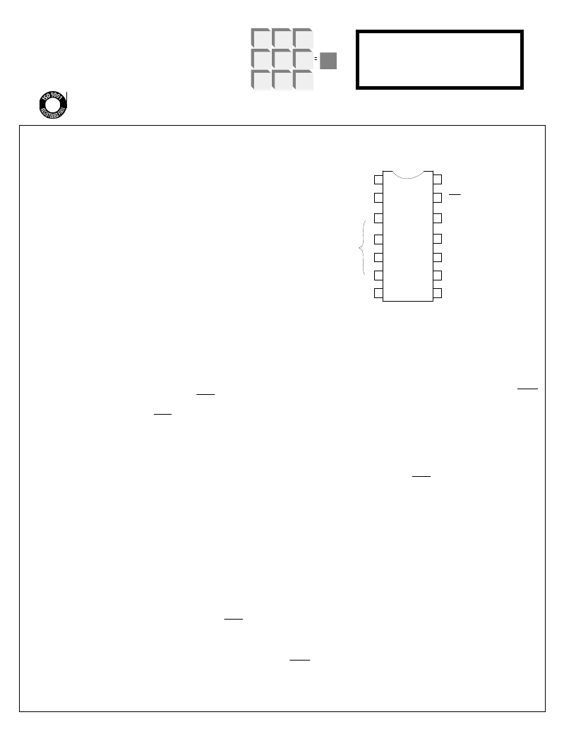
1
2
3
4
5
6
7
L
14
13
12
11
8
9
10
PIN ASSIGNMENT - TOP VIEW
SENSE IN
UNSELECTED KEYS
(RESET)
SELECTED KEYS
(IN SEQUENCE)
LOCK IN
V
SS
(+V)
LOCK OUT
CONVENIENCE
DELAY
SAVE IN
SAVE STATUS OUT
V
DD
(-V)
LOCK STATUS OUT
FIGURE 1.
L
I
1
I
2
I
3
I
4
7220-012703-1
January 2003
UNSELECTED KEYS (RESET) INPUT
(Pin 2)
A high at this input resets the Sequential Detector for the
SELECTED KEYS inputs. This input must be wired to all digit keys
which are not part of the Four-Digit Combination.
SELECTED KEYS INPUTS
(Pins 3, 4, 5, 6)
When these inputs are brought high in correct sequence, (i.e.,I1, I2,
I3, I4) the Sequential Memory is set if SENSE input is high. LOCK
output turns on and LOCK STATUS output turns off when the
Sequential Memory is set.
LOCK INPUT
(Pin 7)
A high at this input resets the Save Memory. The SAVE STATUS
output turns off when this occurs.
LOCK STATUS OUTPUT
(Pin 8)
This output is the complement of LOCK output when the SENSE
input is high. See NOTE.
SAVE STATUS OUTPUT
(Pin 10)
This output turns on when Save Memory is set and SENSE input is
high. See NOTE.
SAVE INPUT
(Pin 11)
A high at this input sets the Save Memory. If Save Memory is set
and Sequential Memory is set, the Save Memory will prevent the
Sequential Memory from being reset as a result of a change at the
SENSE Input. (See SAVE STATUS OUTPUT.)
CONVENIENCE DELAY I/O
(Pin 12)
An external capacitor placed on this pin will delay the effect of
changes at the SENSE Input from affecting the outputs and the
condition of the Sequential Detector and Sequential Memory.
(See Figure 2)
LOCK OUTPUT
(Pin 13)
This output turns on when the Sequential Memory is set and
SENSE input is high. See NOTE.
NOTE
: Outputs are off when SENSE input is low.
LSI/CSI
LSI Computer Systems, Inc. 1235 Walt Whitman Road, Melville, NY 11747 (631) 271-0400 FAX (631) 271-0405
UL
LS7220
A3800
相關PDF資料 |
PDF描述 |
|---|---|
| LS7222 | KEYPAD PROGRAMMABLE DIGITAL LOCK |
| LS7223 | KEYPAD PROGRAMMABLE DIGITAL LOCK |
| LS7225 | DIGITAL LOCK CIRCUIT with Tamper Output |
| LS7226 | DIGITAL LOCK CIRCUIT with Tamper Output |
| LS7231 | TOUCH CONTROL LAMP DIMMER |
相關代理商/技術參數(shù) |
參數(shù)描述 |
|---|---|
| LS7222 | 制造商:LSI 制造商全稱:LSI 功能描述:KEYPAD PROGRAMMABLE DIGITAL LOCK |
| LS7223 | 制造商:LSI 制造商全稱:LSI 功能描述:KEYPAD PROGRAMMABLE DIGITAL LOCK |
| LS7225 | 制造商:LSI 制造商全稱:LSI 功能描述:DIGITAL LOCK CIRCUIT with Tamper Output |
| LS7226 | 制造商:LSI 制造商全稱:LSI 功能描述:DIGITAL LOCK CIRCUIT with Tamper Output |
| LS7228 | 制造商:未知廠家 制造商全稱:未知廠家 功能描述:Address Decoder |
發(fā)布緊急采購,3分鐘左右您將得到回復。