- 您現(xiàn)在的位置:買賣IC網(wǎng) > PDF目錄377664 > LS7220 (LSI Corporation) DIGITAL LOCK FOR AUTOMOTIVE IGNITIONS PDF資料下載
參數(shù)資料
| 型號(hào): | LS7220 |
| 廠商: | LSI Corporation |
| 英文描述: | DIGITAL LOCK FOR AUTOMOTIVE IGNITIONS |
| 中文描述: | 數(shù)字鎖定汽車點(diǎn)火 |
| 文件頁(yè)數(shù): | 4/4頁(yè) |
| 文件大?。?/td> | 63K |
| 代理商: | LS7220 |
SEE NOTE 2
(CONVENIENCE DELAY)
FROM
IGNITION
SWITCH
C (See Note 1)
+12V
SENSE IN
VSS
UNSELECTED
KEYS (RESET)
I
1
I
2
I
3
I
4
LOCK IN
LOCK
CONVENIENCE
DELAY
SAVE IN
SAVE
STATUS
V
DD
LOCK
STATUS
GREEN LED (SAVE INDICATIOR)
RED LED (LOCK INDICATOR)
C1 (See Note 2)
+
RELAY
COIL
(UNLOCK RELAY)
+12V
.05
μ
F,25V
+12V
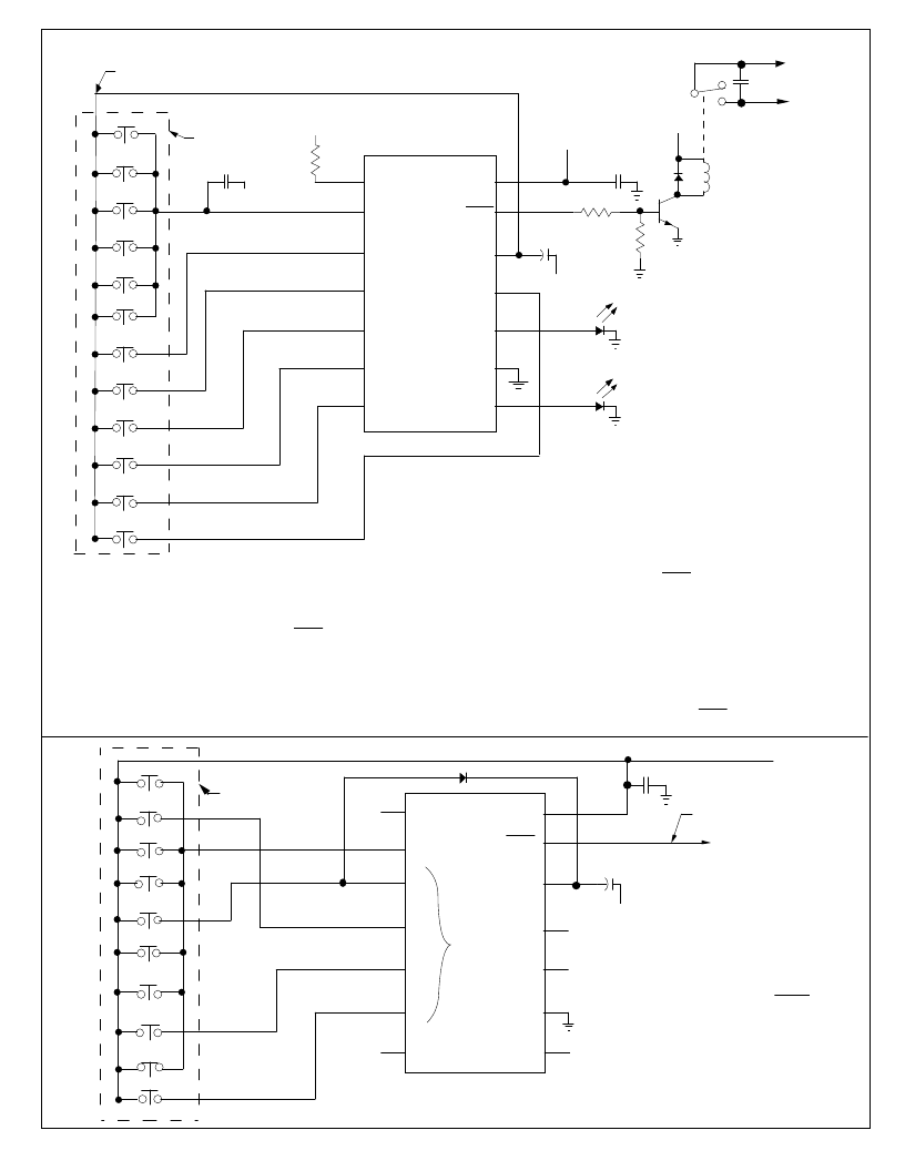
FIGURE 5. TYPICAL ANTI-THEFT DIGITAL LOCK
LS7220
.05
μ
F
250V
KEYPAD
1
2
3
4
5
6
7
8
9
10
11
12
13
14
Note 1
: C is optional. It may be required to prevent ignition noise from
generating a false reset. (Typical values range from 0.1μF to 0.47μF)
Note 2
: See Figure 2 to select C1 value for desired Convenience Delay Time.
If Convenience Delay is not desired, wire Keypad to +12V instead of
CONVENIENCE DELAY and eliminate C1.
To
Starter
Solenoid
or
Starter
Motor
or
Hood Lock
NC
NO
+12V
-
A typical automotive anti-theft digital lock circuit is shown in Figure 5.
When the Ignition Switch is turned on the SENSE input (Pin 1) goes high
and the circuit is ready to accept the unlocking input sequence at I1, I2, I3
and I4 (Pins 3, 4, 5 and 6, respectively). If the keys associated with these
inputs are depressed exactly in sequence, the LOCK output (Pin 13) turns
ON and the Unlock Relay is energized. This state is indicated by the OFF
condition of the LOCK STATUS output (Pin 8) which turns the red LED
OFF (indicates unlock condition). If the keys are depressed in any se-
quence other than as described above, the internal sequential detector re-
sets and the entire sequence must be repeated (See Figure 4).
V
SS
UNSELECTED
KEYS
I
1
I
2
I
3
I
4
CONVENIENCE
DELAY
V
DD
+12V
-
+
C1 (See Note 1)
LS7220
1
2
3
4
5
6
7
8
9
10
11
12
13
14
TO
LOCK CONTROL
CIRCUIT
NOTE 1:
C1 value determines the
Combination Entry Time and
duration of Momentary LOCK
Output (See Figure 4). Select
C1 value from Figure 2. Code
shown is 4179.
See Note 1
See
Note 1
0
1
2
3
4
5
6
7
8
9
.
05μF
FIGURE 6. DIGITAL LOCK WITH MOMENTARY OUTPUT
LOCK
KEYPAD
+12V
In order to save the ON condition of the LOCK output before the ignition switch
is turned Off (i.e., when the SENSE input becomes low) the key associated with
the SAVE input (Pin 11) has to be depressed. The "SAVE" status is indicated
by a high at the SAVE STATUS output (Pin 10), which turns the green LED On.
If the ignition switch is turned Off when the green LED is On, all the output stat-
us are preserved in the internal memory, so that when the ignition switch is
turned on again there is no need to go through the input sequence again. This
feature could be used for valet parking and garage service.
Status saving may be cancelled by depressing the LOCK input key followed by
turning the ignition switch Off for a time greater than the CONVENIENCE
DELAY (See Figure 2). This also turns OFF the LOCK output.
7220-012703-4
相關(guān)PDF資料 |
PDF描述 |
|---|---|
| LS7222 | KEYPAD PROGRAMMABLE DIGITAL LOCK |
| LS7223 | KEYPAD PROGRAMMABLE DIGITAL LOCK |
| LS7225 | DIGITAL LOCK CIRCUIT with Tamper Output |
| LS7226 | DIGITAL LOCK CIRCUIT with Tamper Output |
| LS7231 | TOUCH CONTROL LAMP DIMMER |
相關(guān)代理商/技術(shù)參數(shù) |
參數(shù)描述 |
|---|---|
| LS7222 | 制造商:LSI 制造商全稱:LSI 功能描述:KEYPAD PROGRAMMABLE DIGITAL LOCK |
| LS7223 | 制造商:LSI 制造商全稱:LSI 功能描述:KEYPAD PROGRAMMABLE DIGITAL LOCK |
| LS7225 | 制造商:LSI 制造商全稱:LSI 功能描述:DIGITAL LOCK CIRCUIT with Tamper Output |
| LS7226 | 制造商:LSI 制造商全稱:LSI 功能描述:DIGITAL LOCK CIRCUIT with Tamper Output |
| LS7228 | 制造商:未知廠家 制造商全稱:未知廠家 功能描述:Address Decoder |
發(fā)布緊急采購(gòu),3分鐘左右您將得到回復(fù)。