- 您現(xiàn)在的位置:買賣IC網(wǎng) > PDF目錄377774 > LTC3405 (Linear Technology Corporation) Dual DC/DC Converter with USB Power Manager and Li-Ion Battery Charger PDF資料下載
參數(shù)資料
| 型號: | LTC3405 |
| 廠商: | Linear Technology Corporation |
| 元件分類: | 基準電壓源/電流源 |
| 英文描述: | Dual DC/DC Converter with USB Power Manager and Li-Ion Battery Charger |
| 中文描述: | 雙DC / DC轉(zhuǎn)換器的USB電源管理器和鋰離子電池充電器 |
| 文件頁數(shù): | 11/16頁 |
| 文件大小: | 235K |
| 代理商: | LTC3405 |
11
LTC3405A-1.5/LTC3405A-1.8
sn3405a1518 3405a1518fs
APPLICATIOU
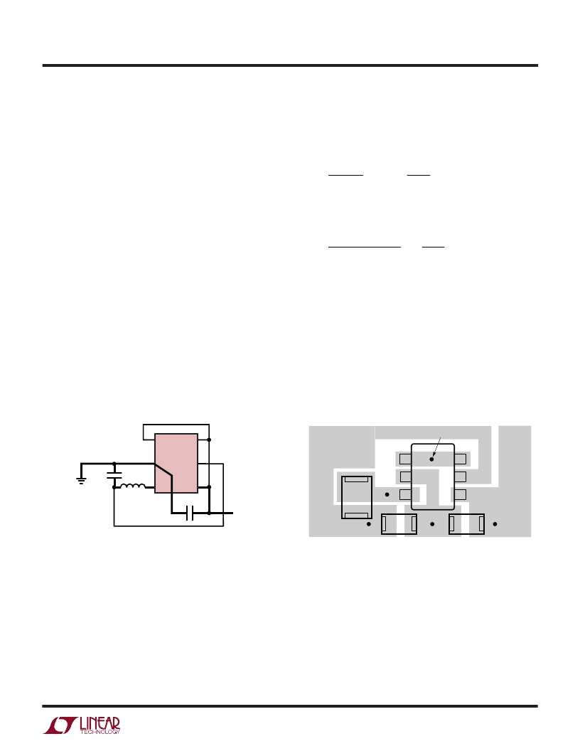
PC Board Layout Checklist
When laying out the printed circuit board, the following
checklist should be used to ensure proper operation of the
LTC3405A series parts. These items are also illustrated
graphically in Figures 4 and 5. Check the following in your
layout:
1. The power traces, consisting of the GND trace, the SW
trace and the V
IN
trace should be kept short, direct and
wide.
2. Does the (+) plate of C
IN
connect to V
IN
as closely as
possible This capacitor provides the AC current to the
internal power MOSFETs.
W
U
U
Figure 4. LTC3405A-1.8 Layout Diagram
Figure 5. LTC3405A-1.8 Suggested Layout
RUN
LTC3405A-1.8
GND
SW
6
L1
BOLD LINES INDICATE HIGH CURRENT PATHS
V
IN
V
OUT
3405A1518 F04
4
5
1
3
+
–
2
MODE
V
OUT
V
IN
C
IN
C
OUT
LTC3405A-1.8
GND
3405A1518 F05
PIN 1
V
OUT
V
IN
SW
VIA TO V
IN
C
OUT
C
IN
L1
3. Keep the (–) plates of C
IN
and C
OUT
as close as possible.
Design Example
As a design example, assume the LTC3405A-1.8 is used
in a single lithium-ion battery-powered cellular phone
application. The V
IN
will be operating from a maximum of
4.2V down to about 2.7V. The load current requirement
is a maximum of 0.25A but most of the time it will be in
standby mode, requiring only 2mA. Efficiency at both low
and high load currents is important. Output voltage is
1.8V. With this information we can calculate L using
equation (1),
V
V
L
IN
)
Substituting V
OUT
= 1.8V, V
IN
= 4.2V,
I
L
= 100mA and
f = 1.5MHz in equation (3) gives:
L
f
I
V
OUT
OUT
=
( )
(
1
1
(3)
L
V
MHz
mA
V
V
H
=
μ
1 8
.
1 5
.
100
(
1
1 8
4 2
.
6 8
.
)
.
For best efficiency choose a 300mA or greater inductor
with less than 0.3
series resistance.
C
IN
will require an RMS current rating of at least 0.125A
I
LOAD(MAX)
/2 at temperature and C
OUT
will require an ESR
of less than 0.5
. In most cases, a tantalum capacitor will
satisfy this requirement.
Figure 6 shows the complete circuit along with its effi-
ciency curve.
相關(guān)PDF資料 |
PDF描述 |
|---|---|
| LTC3405A | Dual DC/DC Converter with USB Power Manager and Li-Ion Battery Charger |
| LTC3405A-1.8 | 1.5V, 1.8V, 1.5MHz, 300mA Synchronous Step-Down Regulators in ThinSOT |
| LTC3406BES5 | 1.5MHz, 600mA Synchronous Step-Down Regulator in ThinSOT |
| LTC3406BES5-1.5 | 256 x 18 3.3-V asynchronous FIFO memory 56-SSOP 0 to 70 |
| LTC3406BES5-1.8 | 1.5MHz, 600mA Synchronous Step-Down Regulator in ThinSOT |
相關(guān)代理商/技術(shù)參數(shù) |
參數(shù)描述 |
|---|---|
| LTC3405A | 制造商:LINER 制造商全稱:Linear Technology 功能描述:1.5MHz, 300mA Synchronous Step-Down Regulator in ThinSOT |
| LTC3405A-1.375 | 制造商:LINER 制造商全稱:Linear Technology 功能描述:1.375V, 1.5MHz, 300mA Synchronous Step-Down Regulators in ThinSOT |
| LTC3405A-1.5 | 制造商:LINER 制造商全稱:Linear Technology 功能描述:1.5V, 1.8V, 1.5MHz, 300mA Synchronous Step-Down Regulators in ThinSOT |
| LTC3405A-1.8 | 制造商:LINER 制造商全稱:Linear Technology 功能描述:1.5V, 1.8V, 1.5MHz, 300mA Synchronous Step-Down Regulators in ThinSOT |
| LTC3405AES6 | 制造商:LINER 制造商全稱:Linear Technology 功能描述:1.5MHz, 300mA Synchronous Step-Down Regulator in ThinSOT |
發(fā)布緊急采購,3分鐘左右您將得到回復(fù)。