- 您現(xiàn)在的位置:買賣IC網(wǎng) > PDF目錄377774 > LTC3405 (Linear Technology Corporation) Dual DC/DC Converter with USB Power Manager and Li-Ion Battery Charger PDF資料下載
參數(shù)資料
| 型號: | LTC3405 |
| 廠商: | Linear Technology Corporation |
| 元件分類: | 基準(zhǔn)電壓源/電流源 |
| 英文描述: | Dual DC/DC Converter with USB Power Manager and Li-Ion Battery Charger |
| 中文描述: | 雙DC / DC轉(zhuǎn)換器的USB電源管理器和鋰離子電池充電器 |
| 文件頁數(shù): | 8/16頁 |
| 文件大小: | 235K |
| 代理商: | LTC3405 |
8
LTC3405A-1.5/LTC3405A-1.8
sn3405a1518 3405a1518fs
APPLICATIOU
The basic LTC3405A series parts application circuit is
shown in Figure 1. External component selection is driven
by the load requirement and begins with the selection of L
followed by C
IN
and C
OUT
.
W
U
U
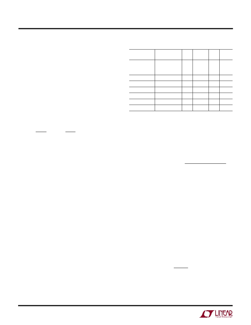
Table 1. Representative Surface Mount Inductors
MAX DC
MANUFACTURER PART NUMBER
Taiyo Yuden
VALUE CURRENT
2.2
μ
H
2.2
μ
H
3.3
μ
H
4.7
μ
H
DCR
0.13
1.6mm
0.23
1.25mm
0.2
0.2
0.2
0.25
1.6mm
0.3
0.36
1.2mm
0.23
1.2mm
HEIGHT
LB2016T2R2M
LB2012T2R2M
LB2016T3R3M
ELT5KT4R7M
LQH32CN2R2M33 4.7
μ
H
LB2016T4R7M
ELT5KT6R8M
ELT5KT100M
CMD4D116R8MC 6.8
μ
H
315mA
240mA
280mA
950mA
450mA
210mA
760mA
680mA
620mA
1.6mm
1.2mm
2mm
Panasonic
Murata
Taiyo Yuden
Panasonic
Panasonic
Sumida
4.7
μ
H
6.8
μ
H
10
μ
H
1.2mm
Inductor Selection
For most applications, the inductor value will fall in the
range of 2.2
μ
H to 10
μ
H. Its value is determined by the
desired ripple current. Large value inductors lower ripple
current and small value inductors result in higher ripple
currents. Higher V
IN
or V
OUT
also increases the ripple
current as shown in equation 1. A reasonable starting point
for setting ripple current is
I
L
= 120mA (40% of 300mA).
=
( )( )
f L
I
V
V
V
L
OUT
OUT
IN
1
1
(1)
The DC current rating of the inductor should be at least
equal to the maximum load current plus half the ripple
current to prevent core saturation. Thus, a 360mA rated
inductor should be enough for most applications (300mA
+ 60mA). For better efficiency, choose a low DC-resistance
inductor.
The inductor value also has an effect on Burst Mode
operation. The transition to low current operation begins
when the inductor current peaks fall to approximately
100mA. Lower inductor values (higher
I
L
) will cause this
to occur at lower load currents, which can cause a dip in
efficiency in the upper range of low current operation. In
Burst Mode operation, lower inductance values will cause
the burst frequency to increase.
Inductor Core Selection
Different core materials and shapes will change the size/
current and price/current relationship of an inductor. Tor-
oid or shielded pot cores in ferrite or permalloy materials
are small and don’t radiate much energy, but generally cost
more than powdered iron core inductors with similar
electrical characteristics. The choice of which style induc-
tor to use often depends more on the price vs size require-
ments and any radiated field/EMI requirements than on
what the LTC3405A series parts require to operate. Table
1 shows some typical surface mount inductors that work
well in LTC3405A series parts applications.
C
IN
and C
OUT
Selection
In continuous mode, the source current of the top MOSFET
is a square wave of duty cycle V
OUT
/V
IN
. To prevent large
voltage transients, a low ESR input capacitor sized for the
maximum RMS current must be used. The maximum
RMS capacitor current is given by:
C
I
V
V
V
V
IN
OMAX
OUT
IN
OUT
IN
required I
RMS
(
)
[
]
1 2
This formula has a maximum at V
IN
= 2V
OUT
, where
I
RMS
= I
OUT
/2. This simple worst-case condition is com-
monly used for design because even significant deviations
do not offer much relief. Note that the capacitor
manufacturer’s ripple current ratings are often based on
2000 hours of life. This makes it advisable to further derate
the capacitor, or choose a capacitor rated at a higher
temperature than required. Always consult the manufac-
turer if there is any question.
The selection of C
OUT
is driven by the required effective
series resistance (ESR). Typically, once the ESR require-
ment for C
OUT
has been met, the RMS current rating
generally far exceeds the I
RIPPLE(P-P)
requirement. The
output ripple
V
OUT
is determined by:
+
V
I ESR
L
fC
OUT
OUT
1
8
where f = operating frequency, C
OUT
= output capacitance
and
I
L
= ripple current in the inductor. For a fixed output
voltage, the output ripple is highest at maximum input
voltage since
I
L
increases with input voltage.
相關(guān)PDF資料 |
PDF描述 |
|---|---|
| LTC3405A | Dual DC/DC Converter with USB Power Manager and Li-Ion Battery Charger |
| LTC3405A-1.8 | 1.5V, 1.8V, 1.5MHz, 300mA Synchronous Step-Down Regulators in ThinSOT |
| LTC3406BES5 | 1.5MHz, 600mA Synchronous Step-Down Regulator in ThinSOT |
| LTC3406BES5-1.5 | 256 x 18 3.3-V asynchronous FIFO memory 56-SSOP 0 to 70 |
| LTC3406BES5-1.8 | 1.5MHz, 600mA Synchronous Step-Down Regulator in ThinSOT |
相關(guān)代理商/技術(shù)參數(shù) |
參數(shù)描述 |
|---|---|
| LTC3405A | 制造商:LINER 制造商全稱:Linear Technology 功能描述:1.5MHz, 300mA Synchronous Step-Down Regulator in ThinSOT |
| LTC3405A-1.375 | 制造商:LINER 制造商全稱:Linear Technology 功能描述:1.375V, 1.5MHz, 300mA Synchronous Step-Down Regulators in ThinSOT |
| LTC3405A-1.5 | 制造商:LINER 制造商全稱:Linear Technology 功能描述:1.5V, 1.8V, 1.5MHz, 300mA Synchronous Step-Down Regulators in ThinSOT |
| LTC3405A-1.8 | 制造商:LINER 制造商全稱:Linear Technology 功能描述:1.5V, 1.8V, 1.5MHz, 300mA Synchronous Step-Down Regulators in ThinSOT |
| LTC3405AES6 | 制造商:LINER 制造商全稱:Linear Technology 功能描述:1.5MHz, 300mA Synchronous Step-Down Regulator in ThinSOT |
發(fā)布緊急采購,3分鐘左右您將得到回復(fù)。