- 您現(xiàn)在的位置:買賣IC網(wǎng) > PDF目錄370837 > M34250M2-116FP (Mitsubishi Electric Corporation) SINGLE-CHIP 4-BIT CMOS MICROCOMPUTER PDF資料下載
參數(shù)資料
| 型號: | M34250M2-116FP |
| 廠商: | Mitsubishi Electric Corporation |
| 英文描述: | SINGLE-CHIP 4-BIT CMOS MICROCOMPUTER |
| 中文描述: | 單芯片4位微機(jī)的CMOS |
| 文件頁數(shù): | 28/58頁 |
| 文件大小: | 331K |
| 代理商: | M34250M2-116FP |
第1頁第2頁第3頁第4頁第5頁第6頁第7頁第8頁第9頁第10頁第11頁第12頁第13頁第14頁第15頁第16頁第17頁第18頁第19頁第20頁第21頁第22頁第23頁第24頁第25頁第26頁第27頁當(dāng)前第28頁第29頁第30頁第31頁第32頁第33頁第34頁第35頁第36頁第37頁第38頁第39頁第40頁第41頁第42頁第43頁第44頁第45頁第46頁第47頁第48頁第49頁第50頁第51頁第52頁第53頁第54頁第55頁第56頁第57頁第58頁

MITSUBISHI
ELECTRIC
28
MITSUBISHI MICROCOMPUTERS
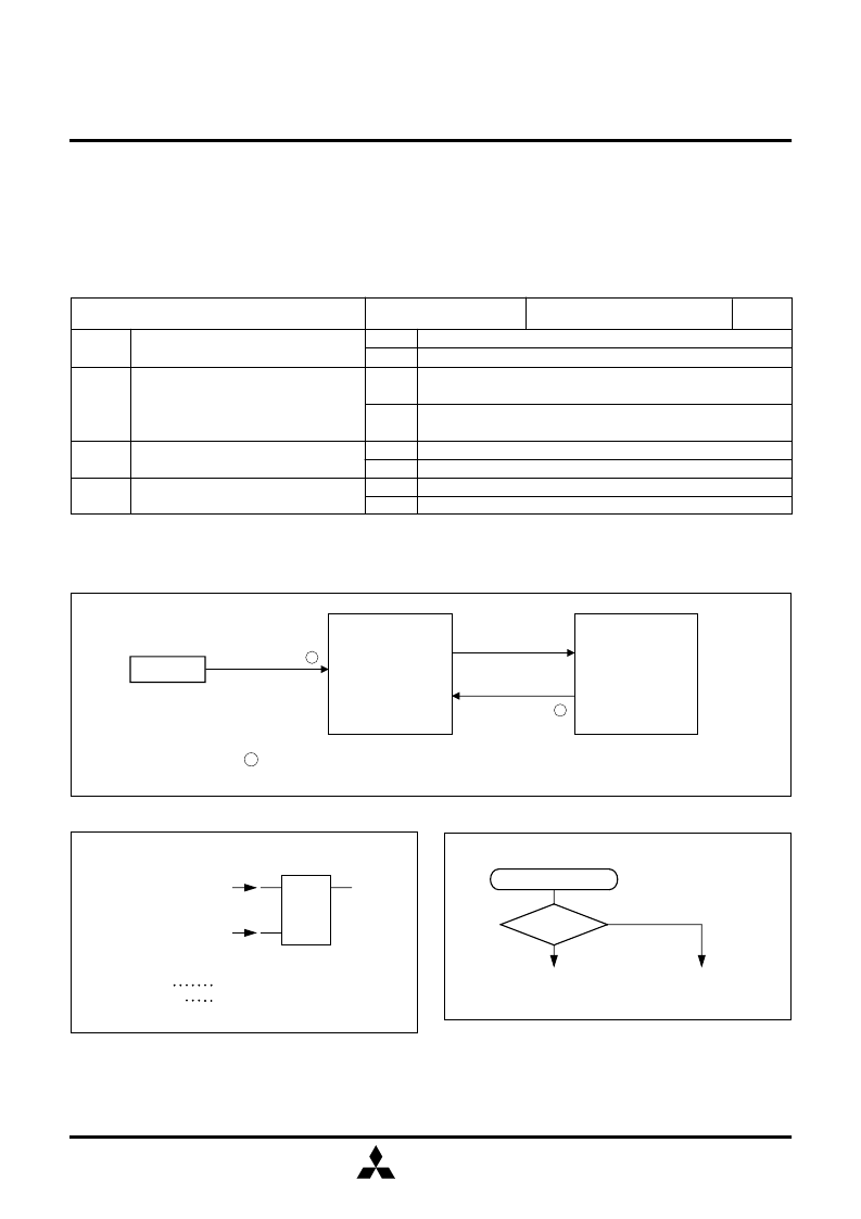
4250 Group
SINGLE-CHIP 4-BIT CMOS MICROCOMPUTER
: Microcomputer starts its operation after 3584 to 3585 machine cycles for the time
required to stabilize the f(X
IN
) oscillation.
Stabilizing time a
POF instruction
is executed
A
f(X
IN
) oscillation
Return input
(Stabilizing time a )
B
(RAM back-up
mode)
f(X
IN
) stop
Reset
(Stabilizing time a )
K0
3
K0
2
K0
1
K0
0
Instruction clock divided by 4
Instruction clock divided by 512
Rising waveform (“L”
→
“H”)
Falling waveform (“H”
→
“L”)
Key-on wakeup not used
Key-on wakeup used (“L” level recognized)
Key-on wakeup not used
Key-on wakeup used (“L” level recognized)
Prescaler dividing ratio selection bit
Interrupt valid waveform for INT pin/
key-on wakeup valid waveform selection
bit (Note 2)
Ports G
1
–G
3
key-on wakeup control bit
Ports S
0
–S
3
key-on wakeup control bit
Key-on wakeup control register K0
at reset : 0000
2
at RAM back-up : state retained
0
1
0
1
0
1
0
1
R/W
Notes 1: “R” represents read enabled, and “W” represents write enabled.
2: Set a value to the bit 2 of register K0, and execute the SNZ0 instruction to clear the EXF0 flag after executing at least one
instruction. According to the input state of G
0
/INT pin, the external interrupt request flag (EXF0) may be set when the
interrupt valid waveform is changed.
Table 14 Key-on wakeup control register
Fig. 24 State transition
S
R
Q
Power down flag P
POF instruction
Reset input
G
Set source POF instruction is executed
G
Clear source Reset input
Fig. 25 Set source and clear source of the P flag
Fig. 26 Start condition identified example using the SNZP
instruction
Software start
P = “1”
Yes
Warm start
Cold start
No
(5) Key-on wakeup control register K0
Key-on wakeup control register K0
The interrupt valid waveform for INT pin/key-on wakeup
valid waveform selection bit, the ports G
1
–G
3
key-on
wakeup control bit and the ports S
0
–S
3
key-on wakeup
control bit are assigned to the register K0. Set the contents
of this register through register A with the TK0A instruction.
The TAK0 instruction can be used to transfer the contents
of register K0 to register A.
相關(guān)PDF資料 |
PDF描述 |
|---|---|
| M34250 | Single Chip 4 Bits CMOS Microcomputer(4位單片機(jī)) |
| M34250E2FP | SINGLE-CHIP 4-BIT CMOS MICROCOMPUTER |
| M34250M2 | SINGLE-CHIP 4-BIT CMOS MICROCOMPUTER |
| M34282M2-064GP | Aluminum Electrolytic Capacitor; Capacitor Type:Computer Grade; Voltage Rating:75VDC; Capacitor Dielectric Material:Aluminum Electrolytic; Operating Temperature Range:-40 C to C; Capacitance:68000uF RoHS Compliant: Yes |
| M34282M1 | SINGLE-CHIP 4-BIT CMOS MICROCOMPUTER |
相關(guān)代理商/技術(shù)參數(shù) |
參數(shù)描述 |
|---|---|
| M34250M2-XXXFP | 制造商:RENESAS 制造商全稱:Renesas Technology Corp 功能描述:SINGLE-CHIP 4-BIT CMOS MICROCOMPUTER |
| M3426 SL002 | 制造商:Alpha Wire 功能描述:CBL 8PR 24AWG SLT 500' |
| M3426 SL005 | 制造商:Alpha Wire 功能描述:CBL 8PR 24AWG SLT 100' |
| M3427-SLATE-500 | 制造商:Alpha Wire 功能描述: |
| M3428 SL001 | 制造商:Alpha Wire 功能描述:CBL 12PR 24AWG SLT 1000' |
發(fā)布緊急采購,3分鐘左右您將得到回復(fù)。