- 您現(xiàn)在的位置:買賣IC網(wǎng) > PDF目錄370847 > M37702S1BFP (Mitsubishi Electric Corporation) Single Chip 16 Bits CMOS Microcomputer(16位單片機) PDF資料下載
參數(shù)資料
| 型號: | M37702S1BFP |
| 廠商: | Mitsubishi Electric Corporation |
| 英文描述: | Single Chip 16 Bits CMOS Microcomputer(16位單片機) |
| 中文描述: | 單片微機16位的CMOS(16位單片機) |
| 文件頁數(shù): | 25/59頁 |
| 文件大?。?/td> | 811K |
| 代理商: | M37702S1BFP |
第1頁第2頁第3頁第4頁第5頁第6頁第7頁第8頁第9頁第10頁第11頁第12頁第13頁第14頁第15頁第16頁第17頁第18頁第19頁第20頁第21頁第22頁第23頁第24頁當前第25頁第26頁第27頁第28頁第29頁第30頁第31頁第32頁第33頁第34頁第35頁第36頁第37頁第38頁第39頁第40頁第41頁第42頁第43頁第44頁第45頁第46頁第47頁第48頁第49頁第50頁第51頁第52頁第53頁第54頁第55頁第56頁第57頁第58頁第59頁
25
MITSUBISHI MICROCOMPUTERS
M37702M2AXXXFP, M37702M2BXXXFP
M37702S1AFP, M37702S1BFP
SINGLE-CHIP 16-BIT CMOS MICROCOMPUTER
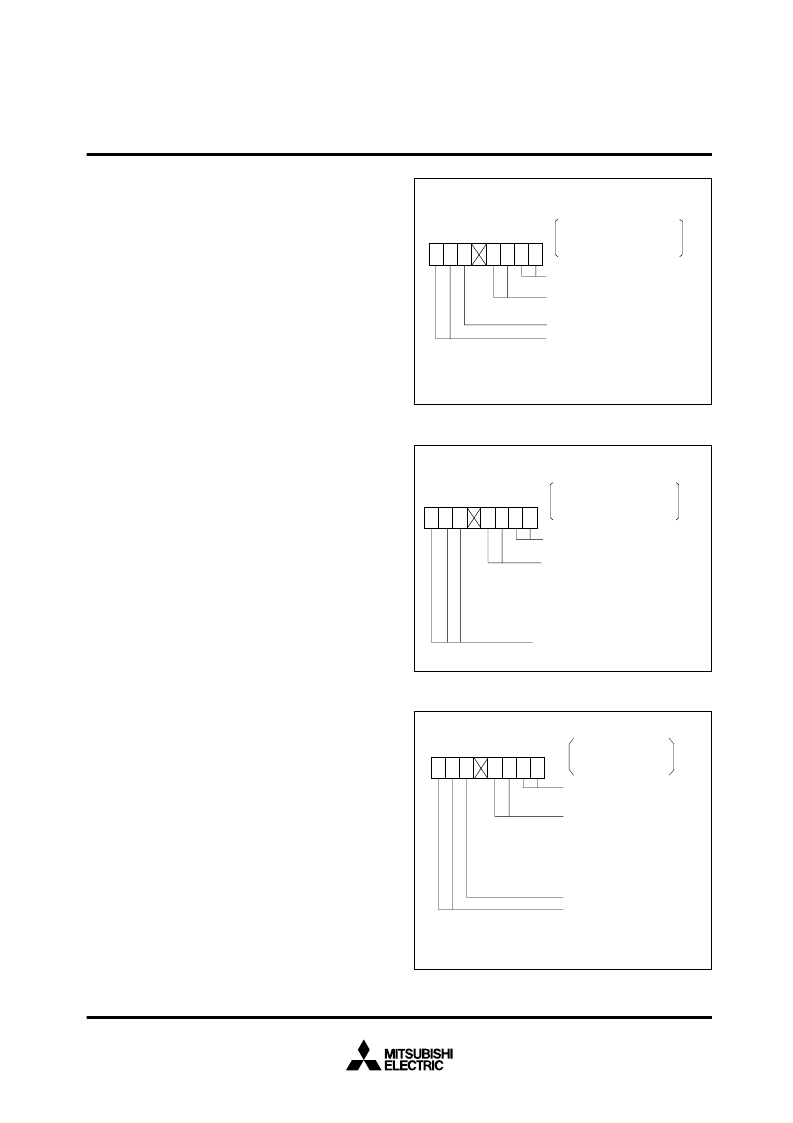
(2) Event counter mode [01]
Figure 29 shows the bit configuration of the timer Bi mode register
during event counter mode. In event counter mode, the bit 0 in the
timer Bi mode register must be “1” and bit 1 must be “0”.
The input signal from the TBi
IN
pin is counted when the count start
flag is “1” and counting is stopped when it is “0”. Count is per-
formed at the fall of the input signal when bits 2, and 3 are “0” and
at the rise of the input signal when bit 3 is “0” and bit 2 is “1”.
When bit 3 is “1” and bit 2 is “0”, count is performed at the rise and
fall of the input signal.
Data write, data read and timer interrupt are performed in the
same way as for timer mode.
(3) Pulse period measurement/pulse width
measurement mode [10]
Figure 30 shows the bit configuration of the timer Bi mode register
during pulse period measurement/pulse width measurement
mode.
In pulse period measurement/pulse width measurement mode, bit
0 must be “0” and bit 1 must be “1”. Bits 6 and 7 are used to select
the clock source. The selected clock is counted when the count
start flag is “1” and counting stops when it is “0”.
The pulse period measurement mode is selected when bit 3 is “0”.
In pulse period measurement mode, the selected clock is counted
during the interval starting at the fall of the input signal from the
TBi
IN
pin to the next fall or at the rise of the input signal to the next
rise and the result is stored in the reload register. In this case, the
reload register acts as a buffer register.
When bit 2 is “0”, the clock is counted from the fall of the input sig-
nal to the next fall. When bit 2 is “1”, the clock is counted from the
rise of the input signal to the next rise.
In the case of counting from the fall of the input signal to the next
fall, counting is performed as follows. As shown in Figure 31,
when the fall of the input signal from TBi
IN
pin is detected, the con-
tents of the counter is transferred to the reload register. Next the
counter is cleared and count is started from the next clock. When
the fall of the next input signal is detected, the contents of the
counter is transferred to the reload register once more, the
counter is cleared, and the count is started. The period from the
fall of the input signal to the next fall is measured in this way.
Fig. 28 Timer Bi mode register bit configuration during timer
mode
Fig. 29 Timer Bi mode register bit configuration during event
counter mode
Fig. 30 Timer Bi mode register bit configuration during pulse
period measurement/pulse width measurement mode
:
Not used in timer mode
Clock source selection bit
0 0 : Select f
2
0 1 : Select f
16
1 0 : Select f
64
1 1 : Select f
512
Timer B0 mode register 5B
16
Timer B1 mode register 5C
16
Timer B2 mode register 5D
16
Addresses
0 0 : Always “00” in timer mode
: Not used in timer mode and
may be any
7 6 5 4 3 2 1 0
0
0
0 1 : Always “01” in event counter
mode
0 0 : Count at the falling edge of input
signal
0 1 : Count at the rising edge of input
signal
1 0 : Count at the both falling edge and
rising edge of input signal
7 6 5 4 3 2
1
0
0
1
Timer B0 mode register 5B
16
Timer B1 mode register 5C
16
Timer B2 mode register 5D
16
Addresses
: Not used in event counter mode
7
6
5
4
3
2
1
0
0
1
1 0 : Always “10” in pulse period
measurement/pulse width
measurement mode
0 0 : Count from the falling edge of
input signal to the next falling one
0 1 : Count from the rising edge of
input signal to the next rising one
1 0 : Count from the falling edge of input
signal to the next rising one
and from the rising edge to the
next falling one
Timer Bi overflow flag
Clock source selection bit
0 0 : Select f
2
0 1 : Select f
16
1 0 : Select f
64
1 1 : Select f
512
Timer B0 mode register 5B
16
Timer B1 mode register 5C
16
Timer B2 mode register 5D
16
Addresses
相關PDF資料 |
PDF描述 |
|---|---|
| M37702M2A | Single Chip 16 Bits CMOS Microcomputer(16位單片機) |
| M37702M2B | Single Chip 16 Bits CMOS Microcomputer(16位單片機) |
| M37702M2AXXXFP | SINGLE-CHIP 16-BIT CMOS MICROCOMPUTER |
| M37702M2A-278FP | SINGLE-CHIP 16-BIT CMOS MICROCOMPUTER |
| M37702M2A-XXXFP | DIODE SCHOTTKY DUAL SERIES 50V 150mW 0.41V-vf 70mA-IFM 1mA-IF 0.1uA-IR SOT-523 3K/REEL |
相關代理商/技術(shù)參數(shù) |
參數(shù)描述 |
|---|---|
| M37702S1LGP | 制造商:MITSUBISHI 制造商全稱:Mitsubishi Electric Semiconductor 功能描述:SINGLE-CHIP 16-BIT CMOS MICROCOMPUTER |
| M37702S1LHP | 制造商:RENESAS 制造商全稱:Renesas Technology Corp 功能描述:SINGLE-CHIP 16-BIT CMOS MICROCOMPUTER |
| M37702S4AFP | 制造商:MITSUBISHI 制造商全稱:Mitsubishi Electric Semiconductor 功能描述:SINGLE-CHIP 16-BIT CMOS MICROCOMPUTER |
| M37702S4BFP | 制造商:MITSUBISHI 制造商全稱:Mitsubishi Electric Semiconductor 功能描述:SINGLE-CHIP 16-BIT CMOS MICROCOMPUTER |
| M37702TL-HPD | 制造商:Renesas Electronics Corporation 功能描述:DEV 7702 GROUP 25MHZ EMUL POD (LOW VOLTA - Bulk |
發(fā)布緊急采購,3分鐘左右您將得到回復。