- 您現(xiàn)在的位置:買賣IC網(wǎng) > PDF目錄359125 > MA4BPS101 PIN Diode Chips with Offset Bond Pads PDF資料下載
參數(shù)資料
| 型號: | MA4BPS101 |
| 英文描述: | PIN Diode Chips with Offset Bond Pads |
| 中文描述: | PIN二極管芯片的邦德片偏移 |
| 文件頁數(shù): | 2/4頁 |
| 文件大小: | 83K |
| 代理商: | MA4BPS101 |

PIN Diode Chips With Offset Bond Pads
MA4BPS101, MA4BPS201, MA4BPS301
M/A-COM Division of AMP Incorporated
Q
North America: Tel. (800) 366-2266, Fax (800) 618-8883
Q
Asia/Pacific: Tel.+85 2 2111 8088, Fax +85 2 2111 8087
Q
Europe: Tel. +44 (1344) 869 595, Fax+44 (1344) 300 020
www.macom.com
AMP and Connecting at a Higher Level are trademarks.
Specifications subject to change without notice.
V2.01
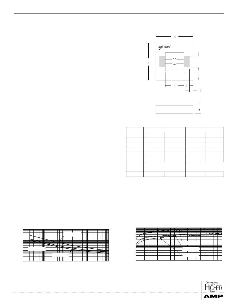
Chip Outline Drawing (ODS-1244)
1,000
10,000
100,000
0.0
2.0
4.0
6.0
8.0
10.0
Re v e r s e Vol t a ge ( Vol t s )
Typical Resistance Curves
Series Resistance vs. Forward Current at 1 GHz
Parallel Resistance vs. Reverse Voltage at 1 GHz
Hanlding and Mounting Information
Handling
All semiconductor dice should be handled with care to avoid
damage or contamination. For an individual die, the use of
plastic tipped tweezers or vacuum pick-up tool is recommended.
When using automatic pick and place, abrasion and mechanical
shock should be minimized.
Mounting
The dice have Ti-Pt-Au back metal, with a final gold thickness
of 0.1 micron. They can be die mounted with a gold-tin eutectic
solder preform or conductive epoxy. The mounting surface
must be clean and flat.
Eutectic Die Attachment
An 80/20 gold-tin eutectic solder preform is recommended with
a work surface temperature of 255
°
C and a tool tip temperature
of 265
°
C. When hot gas is applied, the tool tip temperature
should be 290
°
C. The chip should not be exposed to tempera-
tures greater than 320
°
C for more than 20 seconds. No more
than three seconds should be required for attachment.
Epoxy Die Attachment
A minimum amount of epoxy should be used. A thin epoxy
fillet should be visible around the perimeter of the chip after
placement. Cure epoxy per manufacturer’s schedule.
Wire Bonding
The two bond pads on these die have a Ti-Pt-Au metalization
scheme, with a final gold thickness of 2.5 microns. The pads are
75 x 150 microns; up to two wires or a 100 micron wide ribbon
can be bonded to each pad. Thermosonic wedge wire bonding of
0.001” diameter gold wire is recommended with a stage temper-
ature of 150
°
C and a force of 25 to 40 grams. Ultrasonic energy
should be adjusted to the minimum required.
INCHES
MILLIMETERS
MIN
0.480
0.480
0.140
0.065
0.240
0.180 Ref.
0.050 Ref.
0.110
DIM
A
B
C
D
E
F
G
H
MIN
0.019
0.019
0.0055
0.0026
0.0094
MAX
0.0213
0.0213
0.0063
0.0033
0.0102
MAX
0.540
0.540
0.160
0.085
0.260
0.007 Ref.
0.002 Ref.
0.0043
0.0055
0.140
Notes:
1. Bond pad material: 2.5 micron thick gold.
2. Shaded areas indicate wire bonding pads
3. Backside metal: 0.1 micron thick gold.
0.1
1.0
10.0
100.0
0.0
0.1
1.0
10.0
100.0
F o r w a r d C u r r e n t ( m A )
S
MA4BPS101
MA4BPS201
MA4BPS301
MA4BPS101
MA4BPS201
MA4BPS301
相關(guān)PDF資料 |
PDF描述 |
|---|---|
| MA4E1339SERIES | Silicon Medium Barrier Schottky Diode |
| MA4E185-276 | Stripline Packaged Schottky Mixer Diodes |
| MA4E185-276 | STRIPLINE PACKAGED SCHOTTKY MIXER DIODES |
| MA4E2054 | Surface Mount Low Barrier X-Band Schottky Diode |
| MA4EX370L-1225 | Low Cost Silicon Double Balanced HMIC Mixer 3.0 - 4.0 GHz |
相關(guān)代理商/技術(shù)參數(shù) |
參數(shù)描述 |
|---|---|
| MA4BPS201 | 制造商:M/A-COM Technology Solutions 功能描述:PIN ATTENUATOR/SWIT 70V 2PIN ODS-1244 - Bulk |
| MA4BPS301 | 制造商:M/A-COM Technology Solutions 功能描述:PIN ATTENUATOR/SWIT 70V 2PIN ODS-1244 - Bulk |
| MA4C5 | 制造商:EDAL 制造商全稱:EDAL 功能描述:SILICON GENERAL PURPOSE 3.0 AMP DIODES |
| MA4CM00 | 制造商:TE Connectivity 功能描述: |
| MA4CM01 | 制造商:TE Connectivity 功能描述: |
發(fā)布緊急采購,3分鐘左右您將得到回復(fù)。