- 您現(xiàn)在的位置:買賣IC網(wǎng) > PDF目錄45178 > MAX7359EWA+ (MAXIM INTEGRATED PRODUCTS INC) SPECIALTY MICROPROCESSOR CIRCUIT, PBGA25 PDF資料下載
參數(shù)資料
| 型號: | MAX7359EWA+ |
| 廠商: | MAXIM INTEGRATED PRODUCTS INC |
| 元件分類: | 微控制器/微處理器 |
| 英文描述: | SPECIALTY MICROPROCESSOR CIRCUIT, PBGA25 |
| 封裝: | 2.31 X 2.31 MM, ROHS COMPLIANT, WLP-25 |
| 文件頁數(shù): | 5/20頁 |
| 文件大?。?/td> | 176K |
| 代理商: | MAX7359EWA+ |
Only one autorepeat code is entered into the FIFO, regard-
less of the number of keys pressed. The autorepeat code
continues to be entered in the FIFO at the frequency set by
the bits D4–D1 until another key event is recorded.
Following the key-release event, if any keys are still
pressed, the MAX7359 restarts the autorepeat sequence.
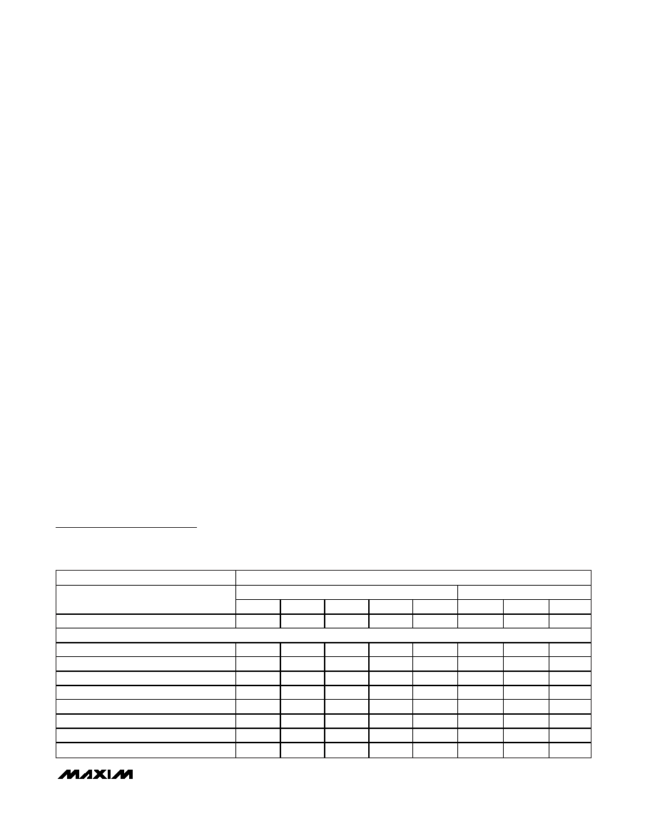
Autosleep Register (0x06)
Autosleep puts the MAX7359 in sleep mode to draw minimal
current. When enabled, the MAX7359 enters sleep mode if
no keys are pressed for the autosleep time (Table 9).
Sleep Mode
In sleep mode, the MAX7359 draws minimal current.
Switch matrix current sources are turned off and pulled
up to VCC. Writing a 0 to D7 in the configuration register
(0x01) puts the device in sleep mode. Writing a 1 to D7
or a key press, when the part is programmed to
autowake, can take the MAX7359 out of sleep mode.
Bit D7 in the configuration register gives the sleep
mode status and can be read anytime. The FIFO data is
maintained while in sleep mode.
Autowake
Key presses initiate autowake and the MAX7359 goes
into operating mode. Key presses that autowake the
MAX7359 are not lost. When a key is pressed while the
MAX7359 is in sleep mode, all analog circuitry, includ-
ing switch matrix current sources, turn on in 2ms. The
initial key needs to be pressed for 2ms plus the
debounce time to be stored in the FIFO. Autowakeup
can be disabled by writing a 0 to D1 in the configura-
tion register (0x01).
Serial Interface
Figure 1 shows the 2-wire serial interface timing details.
Serial Addressing
The MAX7359 operates as a slave that sends and
receives data through an I2C-compatible 2-wire inter-
face. The interface uses a serial-data line (SDA) and a
serial-clock line (SCL) to achieve bidirectional commu-
nication between master(s) and slave(s). A master (typ-
ically a microcontroller) initiates all data transfers to and
from the MAX7359 and generates the SCL clock that
synchronizes the data transfer.
The MAX7359’s SDA line operates as both an input and
an open-drain output. A pullup resistor, typically 4.7k
,
is required on SDA. The MAX7359’s SCL line operates
only as an input. A pullup resistor is required on SCL if
there are multiple masters on the 2-wire interface, or if
the master in a single-master system has an open-drain
SCL output.
Each transmission consists of a START (S) condition
(Figure 2) sent by a master, followed by the MAX7359 7-
bit slave address plus R/W bit, a register address byte, 1
or more data bytes, and finally a STOP (P) condition.
START and STOP Conditions
Both SCL and SDA remain high when the interface is not
busy. A master signals the beginning of a transmission
with a START condition by transitioning SDA from high to
low while SCL is high. When the master has finished
communicating with the slave, it issues a STOP condition
by transitioning SDA from low to high while SCL is high.
The bus is then free for another transmission.
Bit Transfer
One data bit is transferred during each clock pulse
(Figure 3). The data on SDA must remain stable while
SCL is high.
MAX7359
2-Wire Interfaced Low-EMI
Key Switch Controller/GPO
______________________________________________________________________________________
13
REGISTER
REGISTER DATA
RESERVED
AUTOSHUTDOWN TIME
AUTOSLEEP REGISTER
D7
D6
D5
D4
D3
D2
D1
D0
No Autosleep
0
Autosleep for (ms)
8192
0
1
4096
0
1
0
2048
0
1
1024
0
1
0
512
000
00
1
0
1
256
000
00
1
0
256
000
00
1
Power-up default settings
0
1
Table 9. Autosleep Register Format (0x06)
相關(guān)PDF資料 |
PDF描述 |
|---|---|
| MAX7391ANTP | 8 MHz, OTHER CLOCK GENERATOR, PDSO8 |
| MAX7391ANVB | 12 MHz, OTHER CLOCK GENERATOR, PDSO8 |
| MAX7391BMVB | 12 MHz, OTHER CLOCK GENERATOR, PDSO8 |
| MAX7391CNTP | 8 MHz, OTHER CLOCK GENERATOR, PDSO8 |
| MAX7391ANRD | 4 MHz, OTHER CLOCK GENERATOR, PDSO8 |
相關(guān)代理商/技術(shù)參數(shù) |
參數(shù)描述 |
|---|---|
| MAX7359EWA+ | 制造商:Maxim Integrated Products 功能描述:- Rail/Tube |
| MAX7359EWA+T | 功能描述:外圍驅(qū)動器與原件 - PCI 2-WIRE IF LO-EMI KEY SWITCH CNTRLR RoHS:否 制造商:PLX Technology 工作電源電壓: 最大工作溫度: 安裝風(fēng)格:SMD/SMT 封裝 / 箱體:FCBGA-1156 封裝:Tray |
| MAX735C/D | 功能描述:電流型 PWM 控制器 -5V Inverting Current-Mode PWM Regulator RoHS:否 制造商:Texas Instruments 開關(guān)頻率:27 KHz 上升時間: 下降時間: 工作電源電壓:6 V to 15 V 工作電源電流:1.5 mA 輸出端數(shù)量:1 最大工作溫度:+ 105 C 安裝風(fēng)格:SMD/SMT 封裝 / 箱體:TSSOP-14 |
| MAX735CPA | 功能描述:直流/直流開關(guān)調(diào)節(jié)器 5V- Inverting DC/DC Converter RoHS:否 制造商:International Rectifier 最大輸入電壓:21 V 開關(guān)頻率:1.5 MHz 輸出電壓:0.5 V to 0.86 V 輸出電流:4 A 輸出端數(shù)量: 最大工作溫度: 安裝風(fēng)格:SMD/SMT 封裝 / 箱體:PQFN 4 x 5 |
| MAX735CPA+ | 功能描述:直流/直流開關(guān)調(diào)節(jié)器 5V- Inverting DC/DC Converter RoHS:否 制造商:International Rectifier 最大輸入電壓:21 V 開關(guān)頻率:1.5 MHz 輸出電壓:0.5 V to 0.86 V 輸出電流:4 A 輸出端數(shù)量: 最大工作溫度: 安裝風(fēng)格:SMD/SMT 封裝 / 箱體:PQFN 4 x 5 |
發(fā)布緊急采購,3分鐘左右您將得到回復(fù)。