- 您現(xiàn)在的位置:買賣IC網(wǎng) > PDF目錄67960 > MAXQ61CA-XXXX+ (MAXIM INTEGRATED PRODUCTS INC) RISC MICROCONTROLLER, QCC32 PDF資料下載
參數(shù)資料
| 型號: | MAXQ61CA-XXXX+ |
| 廠商: | MAXIM INTEGRATED PRODUCTS INC |
| 元件分類: | 微控制器/微處理器 |
| 英文描述: | RISC MICROCONTROLLER, QCC32 |
| 封裝: | ROHS COMPLAINT, TQFN-32 |
| 文件頁數(shù): | 17/26頁 |
| 文件大小: | 1372K |
| 代理商: | MAXQ61CA-XXXX+ |
16-Bit Microcontroller with Infrared Module
MAXQ61C
24 _____________________________________________________________________________________
Applications Information
The low-power, high-performance RISC architecture of
this device makes it an excellent fit for many portable
or battery-powered applications. It is ideally suited for
applications such as universal remote controls that
require the cost-effective integration of IR transmit/
receive capability.
Grounds and Bypassing
Careful PCB layout significantly minimizes system-level
digital noise that could interact with the microcontroller
or peripheral components. The use of multilayer boards
is essential to allow the use of dedicated power planes.
The area under any digital components should be a con-
tinuous ground plane if possible. Keep bypass capacitor
leads short for best noise rejection and place the capaci-
tors as close to the leads of the devices as possible.
CMOS design guidelines for any semiconductor require
that no pin be taken above VDD or below GND. Violation
of this guideline can result in a hard failure (damage to
the silicon inside the device) or a soft failure (uninten-
tional modification of memory contents). Voltage spikes
above or below the device’s absolute maximum ratings
can potentially cause a devastating IC latchup.
Microcontrollers commonly experience negative volt-
age spikes through either their power pins or general-
purpose I/O pins. Negative voltage spikes on power pins
are especially problematic as they directly couple to the
internal power buses. Devices such as keypads can
conduct electrostatic discharges directly into the micro-
controller and seriously damage the device. System
designers must protect components against these tran-
sients that can corrupt system memory.
Additional Documentation
Designers must have the following documents to fully
use all the features of this device. This data sheet
contains pin descriptions, feature overviews, and elec-
trical specifications. Errata sheets contain deviations
from published specifications. The user’s guides offer
detailed information about device features and opera-
tion. The following documents can be downloaded from
www.maxim-ic.com/microcontrollers.
This MAXQ61C data sheet, which contains electrical/
timing specifications, pin descriptions, and package
information.
The MAXQ61C revision-specific errata sheet (www.maxim-
ic.com/errata).
The MAXQ610 User’s Guide, which contains detailed
information on features and operation, including pro-
gramming.
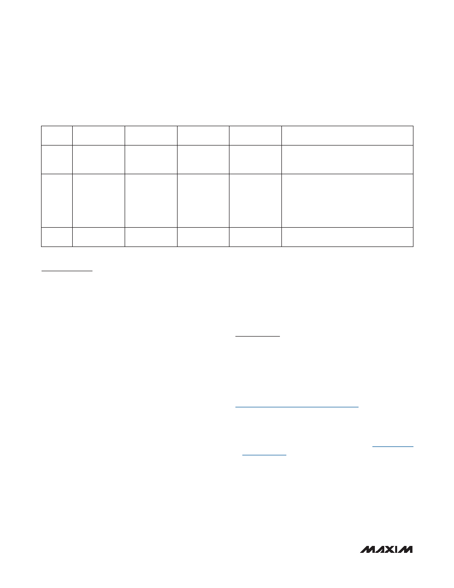
Table 5. Stop Mode Power-Fail Detection States with Power-Fail Monitor Disabled
(continued)
STATE
POWER-FAIL
INTERNAL
REGULATOR
CRYSTAL
OSCILLATOR
SRAM
RETENTION
COMMENTS
D
Off
Yes
Application enters stop mode.
VDD > VRST.
CPU in stop mode.
E
On
(Periodically)
Off
Yes
VPOR < VDD < VRST.
An interrupt occurs that causes the CPU to
exit stop mode.
Power-fail monitor is turned on, detects a
power-fail, and puts CPU in reset.
Power-fail monitor is turned on periodically.
F
Off
—
VDD < VPOR.
Device held in reset. No operation allowed.
相關(guān)PDF資料 |
PDF描述 |
|---|---|
| MAXQ7665BATM+ | 16-BIT, FLASH, 8 MHz, RISC MICROCONTROLLER, QCC48 |
| MB86930-40ZF-G | 32-BIT, 40 MHz, RISC PROCESSOR, CQFP208 |
| MB86930-30ZF-G | 32-BIT, 30 MHz, RISC PROCESSOR, CQFP208 |
| MB86930-40CR-G | 32-BIT, 40 MHz, RISC PROCESSOR, CPGA179 |
| MB881822BPVA1-G-EFE1 | 100 MHz, OTHER CLOCK GENERATOR, PBCC20 |
相關(guān)代理商/技術(shù)參數(shù) |
參數(shù)描述 |
|---|---|
| MAXQ61CE | 制造商:MAXIM 制造商全稱:Maxim Integrated Products 功能描述:16-Bit Microcontroller with Infrared Module |
| MAXQ61CJ | 制造商:MAXIM 制造商全稱:Maxim Integrated Products 功能描述:16-Bit Microcontroller with Infrared Module |
| MAXQ61CK | 制造商:MAXIM 制造商全稱:Maxim Integrated Products 功能描述:16-Bit Microcontroller with Infrared Module |
| MAXQ61CX | 制造商:MAXIM 制造商全稱:Maxim Integrated Products 功能描述:16-Bit Microcontroller with Infrared Module |
| MAXQ61H | 制造商:MAXIM 制造商全稱:Maxim Integrated Products 功能描述:16-Bit Microcontroller with Infrared Module |
發(fā)布緊急采購,3分鐘左右您將得到回復(fù)。