- 您現(xiàn)在的位置:買(mǎi)賣(mài)IC網(wǎng) > PDF目錄69021 > MB90F897YPMT (FUJITSU LTD) 16-BIT, FLASH, 16 MHz, MICROCONTROLLER, PQFP48 PDF資料下載
參數(shù)資料
| 型號(hào): | MB90F897YPMT |
| 廠商: | FUJITSU LTD |
| 元件分類(lèi): | 微控制器/微處理器 |
| 英文描述: | 16-BIT, FLASH, 16 MHz, MICROCONTROLLER, PQFP48 |
| 封裝: | 0.50 MM PITCH, PLASTIC, LQFP-48 |
| 文件頁(yè)數(shù): | 34/52頁(yè) |
| 文件大?。?/td> | 1370K |
| 代理商: | MB90F897YPMT |
第1頁(yè)第2頁(yè)第3頁(yè)第4頁(yè)第5頁(yè)第6頁(yè)第7頁(yè)第8頁(yè)第9頁(yè)第10頁(yè)第11頁(yè)第12頁(yè)第13頁(yè)第14頁(yè)第15頁(yè)第16頁(yè)第17頁(yè)第18頁(yè)第19頁(yè)第20頁(yè)第21頁(yè)第22頁(yè)第23頁(yè)第24頁(yè)第25頁(yè)第26頁(yè)第27頁(yè)第28頁(yè)第29頁(yè)第30頁(yè)第31頁(yè)第32頁(yè)第33頁(yè)當(dāng)前第34頁(yè)第35頁(yè)第36頁(yè)第37頁(yè)第38頁(yè)第39頁(yè)第40頁(yè)第41頁(yè)第42頁(yè)第43頁(yè)第44頁(yè)第45頁(yè)第46頁(yè)第47頁(yè)第48頁(yè)第49頁(yè)第50頁(yè)第51頁(yè)第52頁(yè)

MB90895 Series
4
DS07-13731-5E
(Continued)
*1 : Settings of DIP switch S2 for using emulation pod MB2145-507. For details, see MB2145-507 Hardware Manual
(2.7 Power Pin solely for Emulator).
*2 : MB90F897S/YS
■ PACKAGES AND PRODUCT MODELS
: Yes,
× : No
Note : Refer to “
PACKAGE DIMENSION” for details of the package.
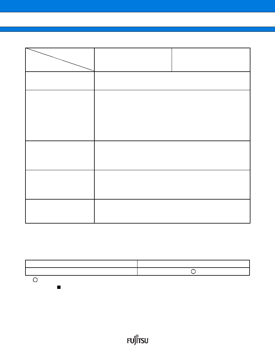
Part number
Parameter
MB90F897
MB90F897S
MB90F897Y (Under development)
MB90F897YS (Under development)
MB90V495G
DTP/External interrupt
Number of inputs: 4
Activated by rising edge, falling edge, “H” level or “L” level input.
External interrupt or extended intelligent I/O service (EI2OS) is available.
8/10-bit A/D converter
Number of channels: 8
Resolution: Selectable 10-bit or 8-bit.
Conversion time: 6.125
μs (at 16-MHz machine clock, including sampling time)
Sequential conversion of two or more successive channels is allowed. (Setting
a maximum of 8 channels is allowed.)
Single conversion mode
: Selected channel is converted only once.
Sequential conversion mode: Selected channel is converted repetitively.
Halt conversion mode
: Conversion of selected channel is stopped and
activated alternately.
UART0 (SCI)
Number of channels: 1
Clock-synchronous transfer: 62.5 kbps to 2 Mbps
Clock-asynchronous transfer: 1,202 bps to 62,500 bps
Communication is allowed by bi-directional serial communication function and
master/slave type connection.
UART1 (SCI)
Number of channels: 1
Clock-synchronous transfer: 62.5 kbps to 2 Mbps
Clock-asynchronous transfer: 9,615 bps to 500 kbps
Communication is allowed by bi-directional serial communication function and
master/slave type connection.
CAN
Complied with Ver 2.0A and Ver 2.0B CAN specifications.
8 built-in message buffers.
Transmission rate of 10 kbps to 1 Mbps (by 16 MHz machine clock)
CAN wake-up
Package
MB90F897/S/Y/YS
FPT-48P-M26
相關(guān)PDF資料 |
PDF描述 |
|---|---|
| MB90F922NCSPMC | MICROCONTROLLER, PQFP120 |
| MB90F922NCPMC | MICROCONTROLLER, PQFP120 |
| MB90F924NCPMC | MICROCONTROLLER, PQFP120 |
| MB90F946APF | MICROCONTROLLER, PQFP100 |
| MB90F947APF | MICROCONTROLLER, PQFP100 |
相關(guān)代理商/技術(shù)參數(shù) |
參數(shù)描述 |
|---|---|
| MB90F947APFR-GS-SPE1 | 制造商:FUJITSU 功能描述: |
| MB90F962SPMCR-GE1 | 制造商:FUJITSU 功能描述:IC MCU 16BIT 16LX 48LQFP |
| MB90F962SPMCR-G-JNE1 | 制造商:FUJITSU 功能描述: |
| MB90V340A-102CR | 制造商:FUJITSU 功能描述: |
| MB-910 | 制造商:Circuit Test 功能描述:BREADBOARD WIRING KIT - 350 PCS |
發(fā)布緊急采購(gòu),3分鐘左右您將得到回復(fù)。