- 您現(xiàn)在的位置:買賣IC網(wǎng) > PDF目錄377930 > MB90V210 (Fujitsu Limited) 8-Bit Proprietary Microcontroller(8位專用微控制器) PDF資料下載
參數(shù)資料
| 型號(hào): | MB90V210 |
| 廠商: | Fujitsu Limited |
| 英文描述: | 8-Bit Proprietary Microcontroller(8位專用微控制器) |
| 中文描述: | 8位微控制器專利(8位專用微控制器) |
| 文件頁數(shù): | 42/99頁 |
| 文件大小: | 932K |
| 代理商: | MB90V210 |
第1頁第2頁第3頁第4頁第5頁第6頁第7頁第8頁第9頁第10頁第11頁第12頁第13頁第14頁第15頁第16頁第17頁第18頁第19頁第20頁第21頁第22頁第23頁第24頁第25頁第26頁第27頁第28頁第29頁第30頁第31頁第32頁第33頁第34頁第35頁第36頁第37頁第38頁第39頁第40頁第41頁當(dāng)前第42頁第43頁第44頁第45頁第46頁第47頁第48頁第49頁第50頁第51頁第52頁第53頁第54頁第55頁第56頁第57頁第58頁第59頁第60頁第61頁第62頁第63頁第64頁第65頁第66頁第67頁第68頁第69頁第70頁第71頁第72頁第73頁第74頁第75頁第76頁第77頁第78頁第79頁第80頁第81頁第82頁第83頁第84頁第85頁第86頁第87頁第88頁第89頁第90頁第91頁第92頁第93頁第94頁第95頁第96頁第97頁第98頁第99頁

MB90210 Series
42
5. A/D Converter
The A/D converter converts the analog input voltage to a digital value. It has the following features:
Conversion time: min.6.125
μ
s per channel (at 16-MHz machine clock)
RC-type successive approximation with built-in sample-and-hold circuit
10-bit or 8-bit resolution
Eight analog input channels programmable for selection
Single conversion mode: Selects and converts one channel.
Scan conversion mode: Converts multiple consecutive channels (up to eight channels programmable).
Consecutive conversion mode: Converts a specified channel repeatedly.
Stop conversion mode: Converts one channel and suspends its own operation until the next activation (allowing
synchronized conversion start).
On completion of A/D conversion, the converter can generate an interrupt request to the CPU. This interrupt
generation can activate the EI
2
OS to transfer the A/D conversion result to memory, making the converter
suitable for continuous operation.
Conversion can be activated by software, external trigger (falling edge), and/or timer (rising edge) as selected.
Use the 16-bit reroad timer 1 channel 3 for the timer.
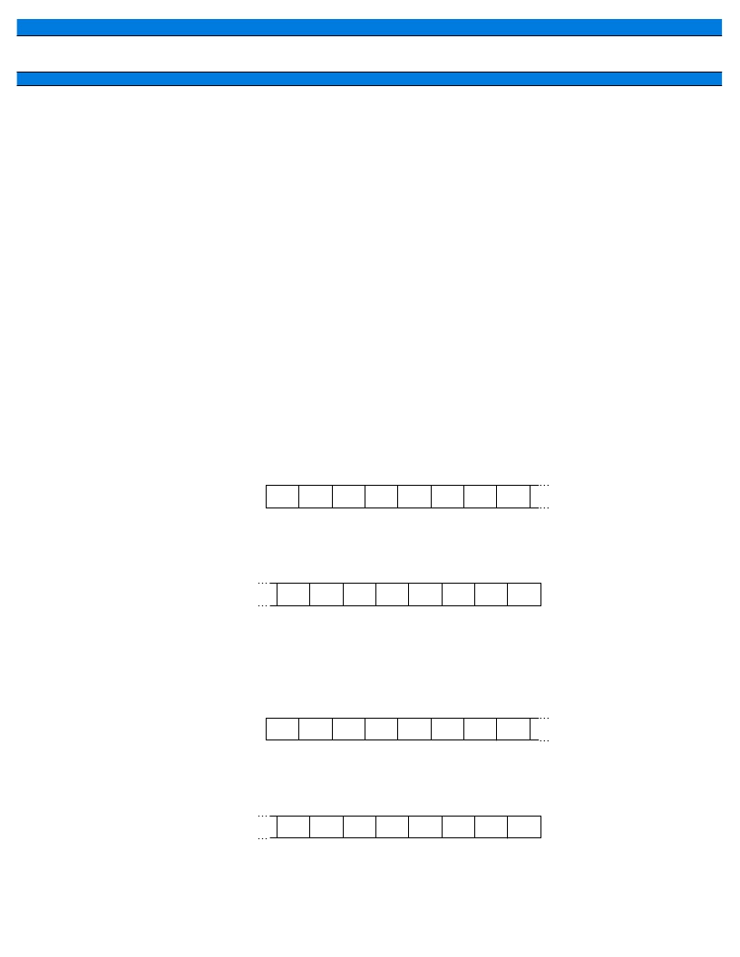
(1) Register Configuration
000035
H
Address:
Control status register (Upper byte)
000034
H
Address:
Control status register (Lower byte)
15
14
13
12
11
10
9
8
7
6
5
4
3
2
1
0
Bit
Bit
MD1
ANE0
ANE1
ANE2
ANS0
ANS1
ANS2
MD0
BUSY
—
STRT
STS0
STS1
PAUS
INTE
INT
ADCS0
ADCS1
(R/W)
(0)
(R/W)
(0)
(R/W)
(0)
(R/W)
(0)
(R/W)
(0)
(W)
(0)
(—)
(0)
(R/W)
(0)
(R/W)
(0)
(R/W)
(0)
(R/W)
(0)
(R/W)
(0)
(R/W)
(0)
(R/W)
(0)
(R/W)
(0)
(R/W)
(0)
Read/write
Initial value
Read/write
Initial value
→
→
→
→
000037
H
Address:
Data register (Upper byte)
000036
H
Address:
Data register (Lower byte)
15
14
13
12
11
10
9
8
7
6
5
4
3
2
1
0
Bit
Bit
D7
D0
D1
D2
D3
D4
D5
D6
S10
D8
D9
—
—
—
—
—
ADCD0
ADCD1
(W)
(0)
(—)
(—)
(—)
(—)
(—)
(—)
(—)
(—)
(R)
(X)
(R)
(X)
(—)
(—)
(R)
(X)
(R)
(X)
(R)
(X)
(R)
(X)
(R)
(X)
(R)
(X)
(R)
(X)
(R)
(X)
Read/write
Initial value
Read/write
Initial value
→
→
→
→
Control status register (ADCS1 and ADCS0)
Data registers (ADCD1 and ADCD0)
相關(guān)PDF資料 |
PDF描述 |
|---|---|
| MB90W214A | 8-Bit Proprietary Microcontroller(8位專用微控制器) |
| MB90W214B | 8-Bit Proprietary Microcontroller(8位專用微控制器) |
| MB90P214BPF | 16-bit Proprietary Microcontroller |
| MB90W214BZF | 16-bit Proprietary Microcontroller |
| MB90W214ZF | 16-bit Proprietary Microcontroller |
相關(guān)代理商/技術(shù)參數(shù) |
參數(shù)描述 |
|---|---|
| MB90V340A-102CR | 制造商:FUJITSU 功能描述: |
| MB-910 | 制造商:Circuit Test 功能描述:BREADBOARD WIRING KIT - 350 PCS |
| MB9100100 | 制造商:COM/DUO 功能描述:FAN 4-6WKS |
| MB9100-100 | 制造商:COM/DUO 功能描述:FAN 4-6WKS |
| MB91101 | 制造商:Panasonic Industrial Company 功能描述:IC |
發(fā)布緊急采購,3分鐘左右您將得到回復(fù)。