- 您現(xiàn)在的位置:買賣IC網(wǎng) > PDF目錄377931 > MB90W234ZFV (FUJITSU LTD) 16-bit Proprietary Microcontroller PDF資料下載
參數(shù)資料
| 型號: | MB90W234ZFV |
| 廠商: | FUJITSU LTD |
| 元件分類: | 微控制器/微處理器 |
| 英文描述: | 16-bit Proprietary Microcontroller |
| 中文描述: | 16-BIT, UVPROM, 16 MHz, MICROCONTROLLER, CQFP100 |
| 封裝: | CERAMIC, LQFP-100 |
| 文件頁數(shù): | 15/83頁 |
| 文件大小: | 1513K |
| 代理商: | MB90W234ZFV |
第1頁第2頁第3頁第4頁第5頁第6頁第7頁第8頁第9頁第10頁第11頁第12頁第13頁第14頁當前第15頁第16頁第17頁第18頁第19頁第20頁第21頁第22頁第23頁第24頁第25頁第26頁第27頁第28頁第29頁第30頁第31頁第32頁第33頁第34頁第35頁第36頁第37頁第38頁第39頁第40頁第41頁第42頁第43頁第44頁第45頁第46頁第47頁第48頁第49頁第50頁第51頁第52頁第53頁第54頁第55頁第56頁第57頁第58頁第59頁第60頁第61頁第62頁第63頁第64頁第65頁第66頁第67頁第68頁第69頁第70頁第71頁第72頁第73頁第74頁第75頁第76頁第77頁第78頁第79頁第80頁第81頁第82頁第83頁
15
MB90230 Series
I
HANDLING DEVICES
1. Preventing Latchup
Latchup may occur on CMOS ICs if voltage higher than V
CC
or lower than V
SS
is applied to input and output pins
other than medium- to high-voltage pins or if higher than the voltage wihich shows on “1. Absolute Maximum
Ratings” in section “
I
Electrical Characteristics” is applied between V
CC
and V
SS
.
When latchup occurs, power supply current increases rapidly and might thermally damage elements. When
using, take great care not to exceed the absolute maximum ratings.
Also, take care to prevent the analog power supply (AV
CC
and AVR) and analog input from exceeding the digital
power supply (V
CC
) when the analog system power supply is turned on and off.
2. Treatment of Unused Pins
Leaving unused input pins open could cause malfunctions. They should be connected to a pull-up or pull-down
resistor.
3. External Reset Input
To reset the internal circuit by the Low-level input to the RST pin, the Low-level input to the RST pin must be
maintained for at least five machine cycles. Pay attention to it if the chip uses external clock input.
4. V
CC
and V
SS
Pins
Apply equal potential to the V
CC
and V
SS
pins.
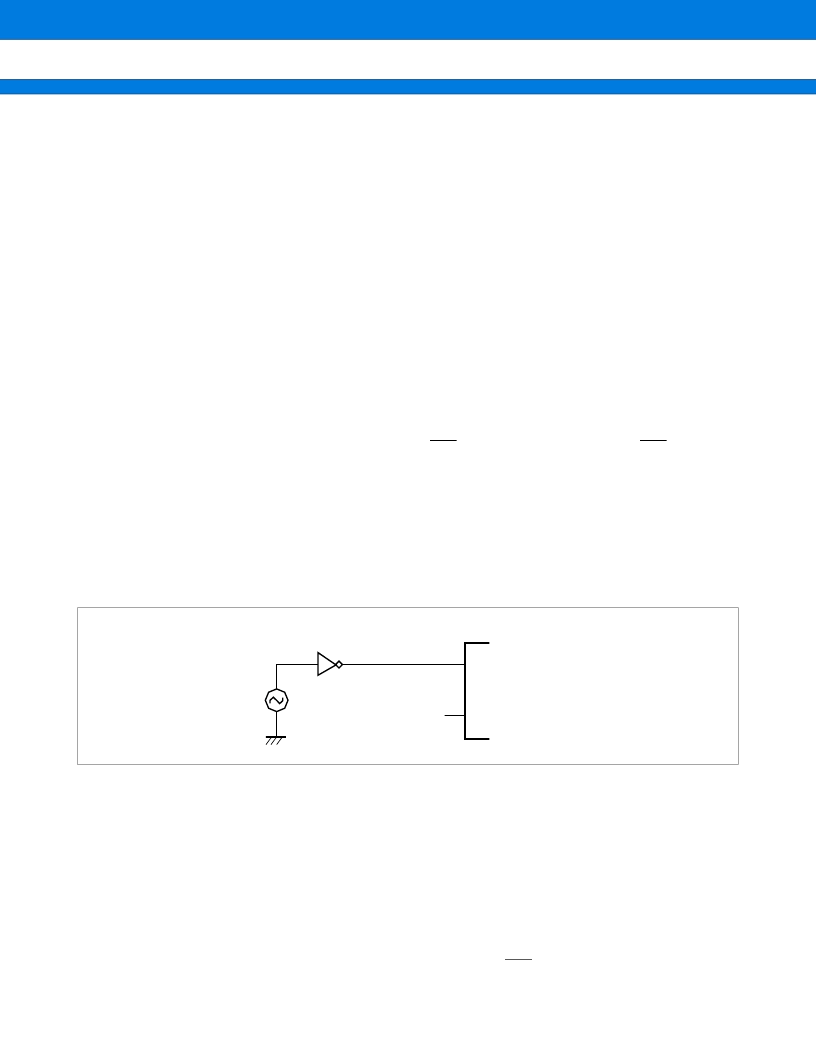
5. Notes on Using an External Clock
When using an external clock, drive the X0 pin as illustrated below:
6. Power-on Sequence for A/D Converter Power Supplies and Analog Inputs
Be sure to turn on the digital power supply (V
CC
) before applying voltage to the A/D converter power supplies
(AV
CC
, AVRH, and AVRL) and analog inputs (AN0 to AN15).
When turning power supplies off, turn off the A/D converter power supplies (AV
CC
, AVRH, and AVRL) and analog
inputs (AN0 to AN15) first, then the digital power supply (AV
CC
).
When turning AVRH on or off, be careful not to let it exceed AV
CC
.
7. Pin set when turning on power supplies
When turning on power supplies, set the hardware standby input pin (HST) to “H”.
Use of External Clock
X0
X1
MB90234
相關(guān)PDF資料 |
PDF描述 |
|---|---|
| MB90W234 | 16-bit Proprietary Microcontroller |
| MB90V230 | 16-bit Proprietary Microcontroller |
| MB90233 | 16-bit Proprietary Microcontroller |
| MB90233PFV | 16-bit Proprietary Microcontroller |
| MB90234PFV | 16-bit Proprietary Microcontroller |
相關(guān)代理商/技術(shù)參數(shù) |
參數(shù)描述 |
|---|---|
| MB-910 | 制造商:Circuit Test 功能描述:BREADBOARD WIRING KIT - 350 PCS |
| MB9100100 | 制造商:COM/DUO 功能描述:FAN 4-6WKS |
| MB9100-100 | 制造商:COM/DUO 功能描述:FAN 4-6WKS |
| MB91101 | 制造商:Panasonic Industrial Company 功能描述:IC |
| MB91101A | 制造商:FUJITSU 制造商全稱:Fujitsu Component Limited. 功能描述:32-bit RISC Microcontroller |
發(fā)布緊急采購,3分鐘左右您將得到回復。