- 您現(xiàn)在的位置:買賣IC網(wǎng) > PDF目錄377931 > MB90W234ZFV (FUJITSU LTD) 16-bit Proprietary Microcontroller PDF資料下載
參數(shù)資料
| 型號(hào): | MB90W234ZFV |
| 廠商: | FUJITSU LTD |
| 元件分類: | 微控制器/微處理器 |
| 英文描述: | 16-bit Proprietary Microcontroller |
| 中文描述: | 16-BIT, UVPROM, 16 MHz, MICROCONTROLLER, CQFP100 |
| 封裝: | CERAMIC, LQFP-100 |
| 文件頁(yè)數(shù): | 61/83頁(yè) |
| 文件大?。?/td> | 1513K |
| 代理商: | MB90W234ZFV |
第1頁(yè)第2頁(yè)第3頁(yè)第4頁(yè)第5頁(yè)第6頁(yè)第7頁(yè)第8頁(yè)第9頁(yè)第10頁(yè)第11頁(yè)第12頁(yè)第13頁(yè)第14頁(yè)第15頁(yè)第16頁(yè)第17頁(yè)第18頁(yè)第19頁(yè)第20頁(yè)第21頁(yè)第22頁(yè)第23頁(yè)第24頁(yè)第25頁(yè)第26頁(yè)第27頁(yè)第28頁(yè)第29頁(yè)第30頁(yè)第31頁(yè)第32頁(yè)第33頁(yè)第34頁(yè)第35頁(yè)第36頁(yè)第37頁(yè)第38頁(yè)第39頁(yè)第40頁(yè)第41頁(yè)第42頁(yè)第43頁(yè)第44頁(yè)第45頁(yè)第46頁(yè)第47頁(yè)第48頁(yè)第49頁(yè)第50頁(yè)第51頁(yè)第52頁(yè)第53頁(yè)第54頁(yè)第55頁(yè)第56頁(yè)第57頁(yè)第58頁(yè)第59頁(yè)第60頁(yè)當(dāng)前第61頁(yè)第62頁(yè)第63頁(yè)第64頁(yè)第65頁(yè)第66頁(yè)第67頁(yè)第68頁(yè)第69頁(yè)第70頁(yè)第71頁(yè)第72頁(yè)第73頁(yè)第74頁(yè)第75頁(yè)第76頁(yè)第77頁(yè)第78頁(yè)第79頁(yè)第80頁(yè)第81頁(yè)第82頁(yè)第83頁(yè)
61
MB90230 Series
I
INSTRUCTIONS (412 INSTRUCTIONS)
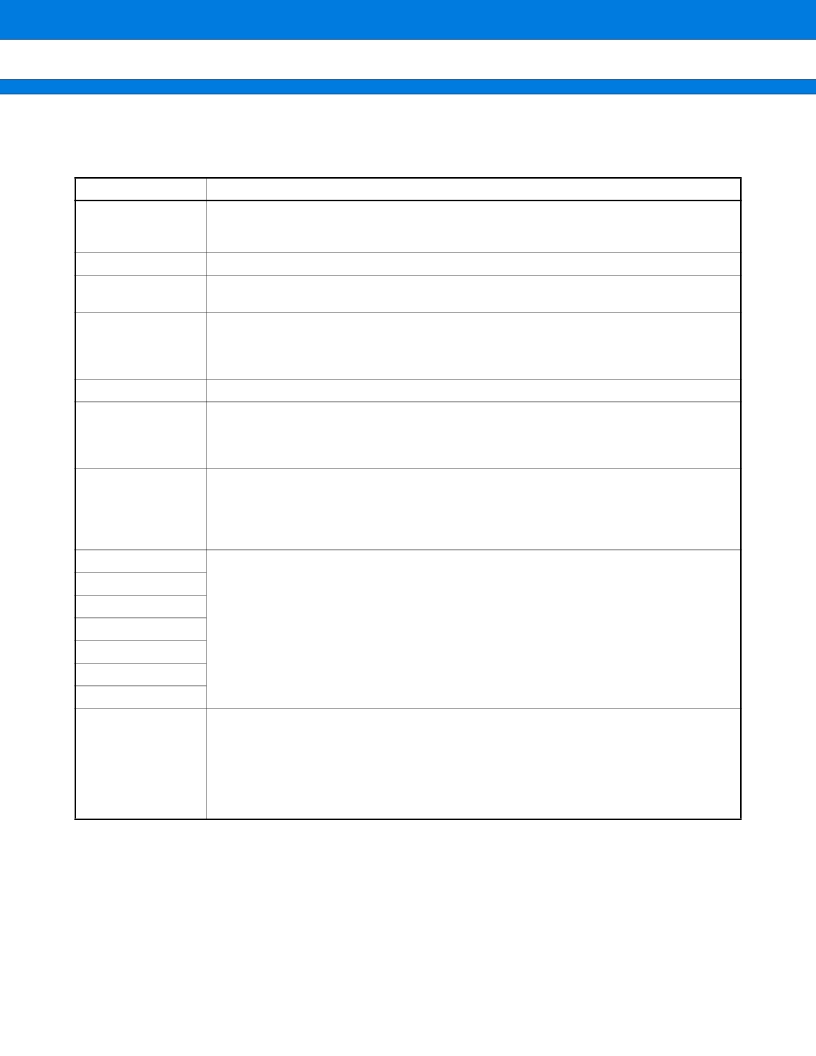
Table 1 Description of Instruction Table
Item
Description
Mnemonic
Upper-case letters and symbols: Described directry in assembly code
Lower-case letters: Replaced when described in assembly code
Numbers after lower-case letters: Indicates the bit width within the code
#
Indicates the number of bytes
~
Indicates the number of cycles
See Table 4 for details about meanings of letters in items.
B
Indicates the compensation value for calculating the number of actual cycles during
execution of instruction.
The number of actual cycles during execution of instruction is summed with the value in
the “cycles” column.
Operation
Indicates operation of instruction.
LH
Indicates special operations involving the bits 15 through 08 of the accumulator.
Z: Transfers “0”
X: Extends before transferring
—: No transfer
AH
Indicates special operations involving the high-order 16 bits in the accumulator.
*: Transfers from AL to AH
—: No transfer
Z: Transfers 00
H
to AH.
X: Transfers 00
H
or FF
H
to AH by extending AL
I
Indicates the status of each of the following flags: I (interrupt enable), S (stack), T (sticky
bit), N (negative), Z (zero), V (overflow), and C (carry).
*: Changes due to execution of instruction.
—: No change.
S: Set by execution of instruction.
R: Reset by execution of instruction.
S
T
N
Z
V
C
RMW
Indicates whether the instruction is a read-modify-write instruction (a single instruction
that reads data from memory, etc., processes the data, and then writes the result to
memory.).
*: Instruction is a read-modify-write instruction
—: Instruction is not a read-modify-write instruction
Note: Cannot be used for addresses that have different meanings depending on
whether they are read or written.
相關(guān)PDF資料 |
PDF描述 |
|---|---|
| MB90W234 | 16-bit Proprietary Microcontroller |
| MB90V230 | 16-bit Proprietary Microcontroller |
| MB90233 | 16-bit Proprietary Microcontroller |
| MB90233PFV | 16-bit Proprietary Microcontroller |
| MB90234PFV | 16-bit Proprietary Microcontroller |
相關(guān)代理商/技術(shù)參數(shù) |
參數(shù)描述 |
|---|---|
| MB-910 | 制造商:Circuit Test 功能描述:BREADBOARD WIRING KIT - 350 PCS |
| MB9100100 | 制造商:COM/DUO 功能描述:FAN 4-6WKS |
| MB9100-100 | 制造商:COM/DUO 功能描述:FAN 4-6WKS |
| MB91101 | 制造商:Panasonic Industrial Company 功能描述:IC |
| MB91101A | 制造商:FUJITSU 制造商全稱:Fujitsu Component Limited. 功能描述:32-bit RISC Microcontroller |
發(fā)布緊急采購(gòu),3分鐘左右您將得到回復(fù)。