- 您現(xiàn)在的位置:買賣IC網(wǎng) > PDF目錄67963 > MB95F118BWPMT 8-BIT, FLASH, 16.25 MHz, MICROCONTROLLER, PQFP48 PDF資料下載
參數(shù)資料
| 型號(hào): | MB95F118BWPMT |
| 元件分類: | 微控制器/微處理器 |
| 英文描述: | 8-BIT, FLASH, 16.25 MHz, MICROCONTROLLER, PQFP48 |
| 封裝: | 7 X 7 MM, 1.70 MM HEIGHT, 0.50 MM PITCH, PLASTIC, LFQFP-48 |
| 文件頁數(shù): | 55/68頁 |
| 文件大小: | 2637K |
| 代理商: | MB95F118BWPMT |
第1頁第2頁第3頁第4頁第5頁第6頁第7頁第8頁第9頁第10頁第11頁第12頁第13頁第14頁第15頁第16頁第17頁第18頁第19頁第20頁第21頁第22頁第23頁第24頁第25頁第26頁第27頁第28頁第29頁第30頁第31頁第32頁第33頁第34頁第35頁第36頁第37頁第38頁第39頁第40頁第41頁第42頁第43頁第44頁第45頁第46頁第47頁第48頁第49頁第50頁第51頁第52頁第53頁第54頁當(dāng)前第55頁第56頁第57頁第58頁第59頁第60頁第61頁第62頁第63頁第64頁第65頁第66頁第67頁第68頁
MB95110B Series
DS07-12615-3E
59
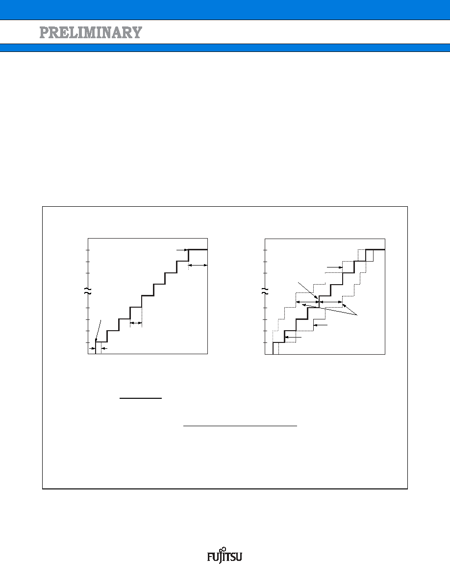
(3) Definition of A/D Converter Terms
Resolution
The level of analog variation that can be distinguished by the A/D converter.
When the number of bits is 10, analog voltage can be divided into 210
= 1024.
Linearity error (unit : LSB)
The deviation between the value along a straight line connecting the zero transition point
(“00 0000 0000”
← → “00 0000 0001”) of a device and the full-scale transition point
(“11 1111 1111”
← → “11 1111 1110”) compared with the actual conversion values obtained.
Differential linear error (Unit : LSB)
Deviation of input voltage, which is required for changing output code by 1 LSB, from an ideal value.
Total error (unit: LSB)
Difference between actual and theoretical values, caused by a zero transition error, full-scale transition error,
linearity error, quantum error, and noise.
(Continued)
VFST
1.5 LSB
3FFH
3FEH
3FDH
004H
003H
002H
001H
1 LSB
0.5 LSB
VOT
AVSS
AVCC
3FFH
3FEH
3FDH
004H
003H
002H
001H
AVSS
VNT
AVCC
{1 LSB
× (N 1) + 0.5 LSB}
1 LSB
= AVCC AVSS
1024
[LSB]
Total error of digital output N
=
VNT
{1 LSB × (N 1) + 0.5 LSB}
1 LSB
Ideal I/O characteristics
Total error
Digit
al
ou
tp
ut
Di
git
al
out
p
ut
Analog input
N
: A/D converter digital output value
VNT : A voltage at which digital output transits from (N
1) to N.
(V)
Actual conversion
characteristic
Actual conversion
characteristic
Ideal characteristics
發(fā)布緊急采購,3分鐘左右您將得到回復(fù)。