- 您現(xiàn)在的位置:買(mǎi)賣(mài)IC網(wǎng) > PDF目錄371008 > MC13109A (Motorola, Inc.) UNIVERSAL CORDLESS TELEPHONE SUBSYSTEM IC PDF資料下載
參數(shù)資料
| 型號(hào): | MC13109A |
| 廠商: | Motorola, Inc. |
| 英文描述: | UNIVERSAL CORDLESS TELEPHONE SUBSYSTEM IC |
| 中文描述: | 通用無(wú)繩電話子系統(tǒng)集成電路 |
| 文件頁(yè)數(shù): | 23/28頁(yè) |
| 文件大小: | 1307K |
| 代理商: | MC13109A |
第1頁(yè)第2頁(yè)第3頁(yè)第4頁(yè)第5頁(yè)第6頁(yè)第7頁(yè)第8頁(yè)第9頁(yè)第10頁(yè)第11頁(yè)第12頁(yè)第13頁(yè)第14頁(yè)第15頁(yè)第16頁(yè)第17頁(yè)第18頁(yè)第19頁(yè)第20頁(yè)第21頁(yè)第22頁(yè)當(dāng)前第23頁(yè)第24頁(yè)第25頁(yè)第26頁(yè)第27頁(yè)第28頁(yè)

MC13109A
23
MOTOROLA RF/IF DEVICE DATA
áááááááááááááááááááááááááááááááááá
áááááááááááááááááááááááááááááááááá
á
áááááááááááááááááááááááááááááá
áááááááááááááááááááááááááááááá
ááááááá
áááááááááááááááááááááááááááááá
áááááááááááááááááááááááááááááá
áááááááááááááááááááááááááááááá
ááááááá
áááááááááááááááááááááááááááááá
áááááááááááááááááááááááááááááá
á
áááááááááááááááááááááááááááááááááá
Figure 27. Test Mode Description
á
á
á
value is Divisor (7;2) (the upper 6 bits of the divisor). If Divisor (7;0) < 16 and Divisor (3;2) > = 2, then output divisor value is Divisor (3;2) (bits 2 and 3
á
á
á
á
á
á
á
ááááááá
Counter Under Test or
á
ááá
“Tx VCO”
á
áááááááááá
á
áááááááááááááááááááááááááááááá
áááááááááááááááááááááááááááááá
áááááááááááááááááááááááááááááááááá
áááááááááááááááááááááááááááááááá
áááááááááááááááááááááááá
áááááááááááááááááááááááá
á
Test Modes
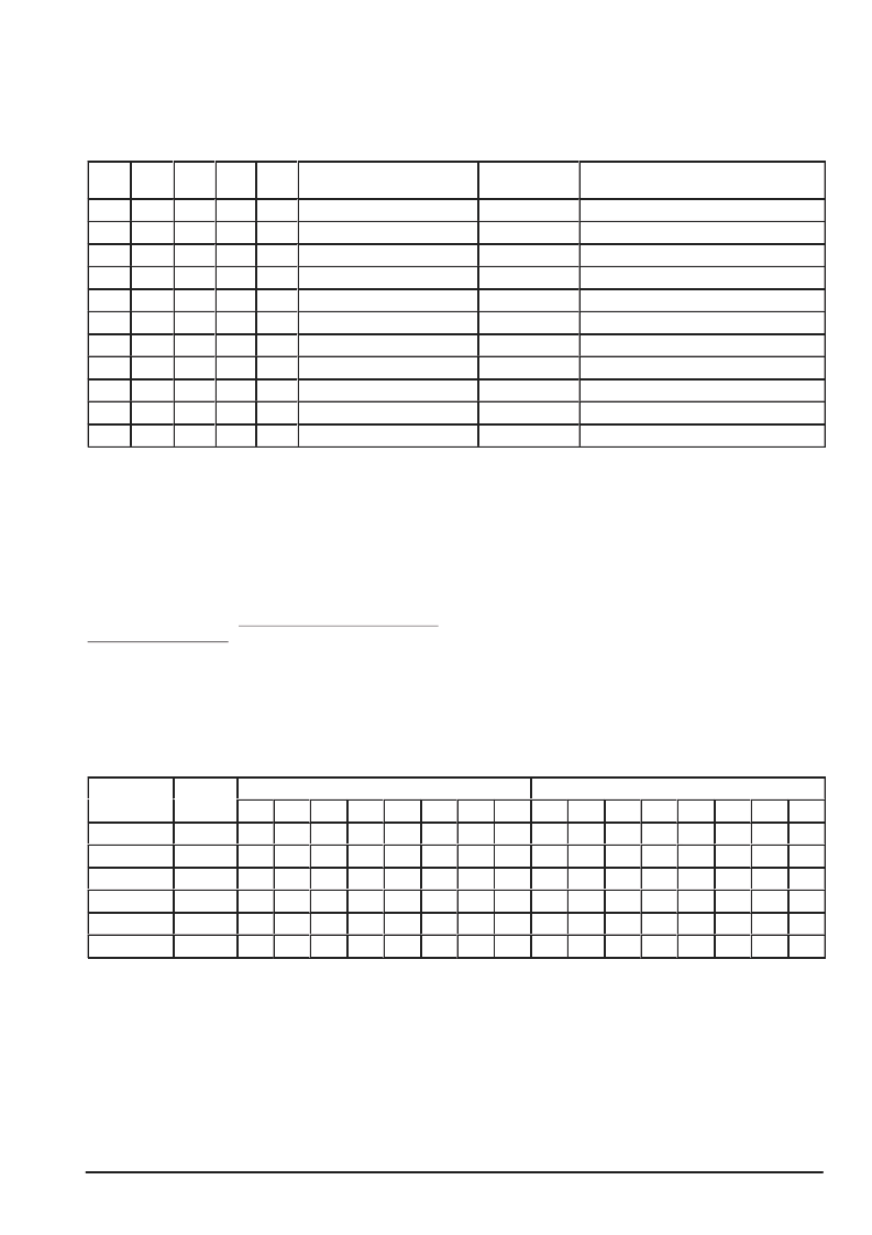
Test Mode Control latch bits enable independent testing of
internal counters and set AGC Gain Options. In test mode,
the “Tx VCO” input pin is multiplexed to the input of the
counter under test and the output of the counter under test is
multiplexed to the “Clk Out” output pin so that each counter
can be individually tested. Make sure test mode bits are set to
“0” for normal operation. Test mode operation is described in
Figure 27. During normal operation and when testing the Tx
Prescaler, the “Tx VCO” input can be a minimum of 200 mVpp
at 80 MHz and should be ac coupled. For other test modes,
input signals should be standard logic levels of 0 to 2.2 V and
a maximum frequency of 16 MHz.
Power–Up Defaults for Control and Counter Registers
When the IC is first powered up, all latch registers are
initialized to a defined state. The MC13109A is initially placed
in the Rx mode with all mutes active and nothing disabled.
The reference counter is set to generate a 5.0 kHz reference
frequency from a 10.24 MHz crystal. The MPU clock output
divider is set to 10 to give the minimum clock output
frequency. The Tx and Rx latch registers are set for USA
Channel Frequency #21. Figure 28 shows the initial
power–up states for all latch registers.
áááááááááááááááááááááááááááááááááá
áááááááááááááááááááááááááááááááááá
ááááááááááááááááááááááááááááááá
ááááááááááááá
ááááááááááááááá
ááááááááááááááá
ááááááááááááááá
ááááááááááá
áááááááááááááááááááááááááááááááá
Register
áááááááááááááááá
ááááá
Count
15
14
13
ááááááááááááááá
1
12
áááááááááááááá
11
10
áááá
9
áááááá
áááááá
ááááááááá
ááááááááá
áááá
áááá
–
1
0
0
1
1
Rx
7215
–
0
ááááááááááááááááááááá
ááááááááááááááááááááá
ááááááááááááááááááááá
1
0
0
0
1
0
1
1
ááááááááááááááááááááááááááááááá
Ref
2048
–
–
0
0
1
0
–
0
0
0
0
0
0
0
–
0
Gain
N/A
–
–
–
–
–
–
–
–
1
1
0
0
相關(guān)PDF資料 |
PDF描述 |
|---|---|
| MC13109AFB | UNIVERSAL CORDLESS TELEPHONE SUBSYSTEM IC |
| MC13109AFTA | UNIVERSAL CORDLESS TELEPHONE SUBSYSTEM IC |
| MC13110A | Narrowband FM IF Receiver(窄頻帶FM IF 接收器) |
| MC13111A | Narrowband FM IF Receiver(窄頻帶FM IF 接收器) |
| MC13111BFTA | UNIVERSAL NARROWBAND FM RECEIVER INTEGRATED CIRCUIT |
相關(guān)代理商/技術(shù)參數(shù) |
參數(shù)描述 |
|---|---|
| MC13109AFB | 制造商:MOTOROLA 制造商全稱:Motorola, Inc 功能描述:UNIVERSAL CORDLESS TELEPHONE SUBSYSTEM IC |
| MC13109AFTA | 制造商:MOTOROLA 制造商全稱:Motorola, Inc 功能描述:UNIVERSAL CORDLESS TELEPHONE SUBSYSTEM IC |
| MC13109FB | 制造商:MOTOROLA 制造商全稱:Motorola, Inc 功能描述:Universal Cordless Telephone Subsystem IC |
| MC13109FTA | 制造商:MOTOROLA 制造商全稱:Motorola, Inc 功能描述:Universal Cordless Telephone Subsystem IC |
| MC1310DIN | 功能描述:電源線濾波器 Filter 500V 10A RoHS:否 制造商:EPCOS 電壓額定值:277 VAC 電流額定值:100 A 安裝風(fēng)格:Chassis 端接類型:Screw |
發(fā)布緊急采購(gòu),3分鐘左右您將得到回復(fù)。