- 您現(xiàn)在的位置:買(mǎi)賣(mài)IC網(wǎng) > PDF目錄378661 > MC44011FB (MOTOROLA INC) BUS CONTROLLED MULTISTANDARD VIDEO PROCESSOR PDF資料下載
參數(shù)資料
| 型號(hào): | MC44011FB |
| 廠商: | MOTOROLA INC |
| 元件分類(lèi): | 消費(fèi)家電 |
| 英文描述: | BUS CONTROLLED MULTISTANDARD VIDEO PROCESSOR |
| 中文描述: | SPECIALTY CONSUMER CIRCUIT, PQFP44 |
| 封裝: | PLASTIC, QFP-44 |
| 文件頁(yè)數(shù): | 37/52頁(yè) |
| 文件大小: | 835K |
| 代理商: | MC44011FB |
第1頁(yè)第2頁(yè)第3頁(yè)第4頁(yè)第5頁(yè)第6頁(yè)第7頁(yè)第8頁(yè)第9頁(yè)第10頁(yè)第11頁(yè)第12頁(yè)第13頁(yè)第14頁(yè)第15頁(yè)第16頁(yè)第17頁(yè)第18頁(yè)第19頁(yè)第20頁(yè)第21頁(yè)第22頁(yè)第23頁(yè)第24頁(yè)第25頁(yè)第26頁(yè)第27頁(yè)第28頁(yè)第29頁(yè)第30頁(yè)第31頁(yè)第32頁(yè)第33頁(yè)第34頁(yè)第35頁(yè)第36頁(yè)當(dāng)前第37頁(yè)第38頁(yè)第39頁(yè)第40頁(yè)第41頁(yè)第42頁(yè)第43頁(yè)第44頁(yè)第45頁(yè)第46頁(yè)第47頁(yè)第48頁(yè)第49頁(yè)第50頁(yè)第51頁(yè)第52頁(yè)
MC44011
37
MOTOROLA ANALOG IC DEVICE DATA
APPLICATIONS INFORMATION
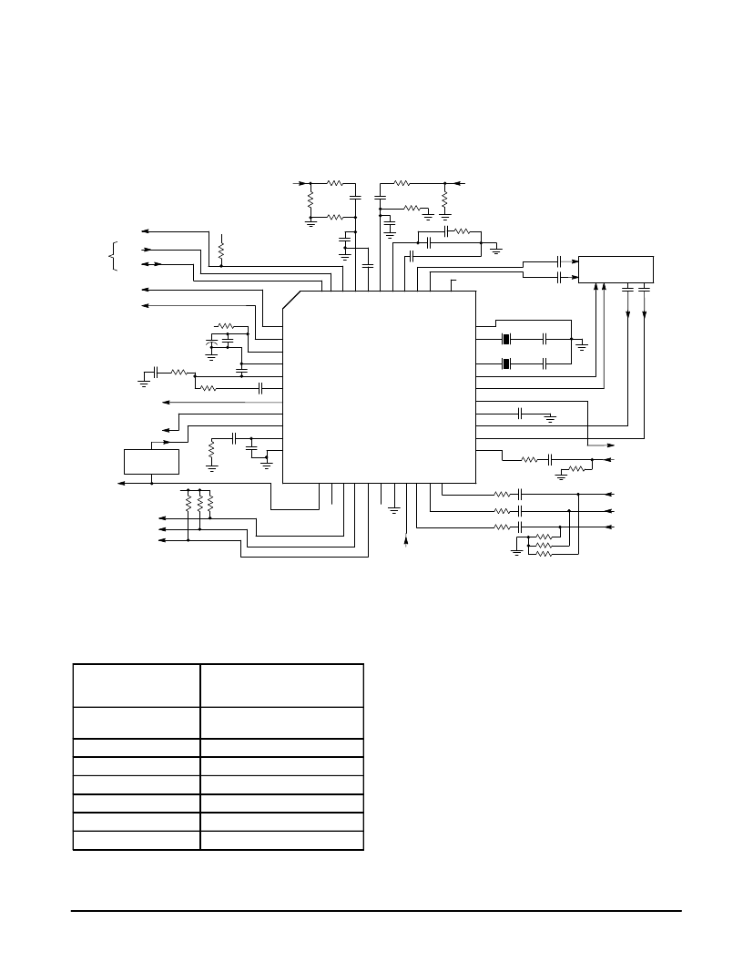
Design Procedure and PC Board Layout
The external components required by the MC44011 are
shown in Figure 42. Except for the crystals, all the
components are standard value resistors and capacitors, and
can be non–precision. Table 18 describes the external
components for each pin.
C
V
C
V
C
V
Video 1
Input
68 pF
110 k
5.0
2.2
μ
/0.01
0.1
100 k
16Fh/CSync
Out
Fh Ref
Blue Out
Green Out
Red Out
Pixel
Clock
MC44140
Delay Line
0.1
(If necessary – see text)
1.0
1.0
0.1
20 pF
20 pF
17.7 MHz
14.3 MHz
0.47
Y1 Luma Out
Y2 Luma Input
Blue In
Green In
Red In
75 Ea
75
0.22
220
0.22
0.22
0.22
12 k
470 pF
10 k
47 nF
4700 pF
390 ea
Fast
Commutate
220
220
220
29
30
31
32
33
34
35
36
37
38
39
17
16
15
14
13
12
11
10
9
8
7
2200 pF
0.1
47 pF
0.1
47 k
75
10 M
470
0.47
47 pF
10 M
0.47
470
Video 2
Input
75
10 k
5.0
I2C
Bus
Burst Gate Out
Field ID Out
SDL
SCL
MC44011
Y2 In
B–Y I/P
R–Y I/P
Y 1 Clmp
Y 1 Out
Sys Sel
SANDC
Xtal 2
N/C
Xtal 1
Gnd
Gnd
PLL Filt
15 k Ref
FH Ref
16Fh/CSync
PLL 1 Filt SW
PLL 1 Filt
Q Gnd
Iref
Burst G
FLD ID
VSync Out
C
R
G
B
G
B
F
R
G
S
S
V
V
A
V
4
R
I
B
Frequency
Divider
5.0
1
1
2
2
2
2
2
2
2
2
2
5
5
6
4
5
3
2
1
4
4
4
4
4
5.0
Figure 42. Basic Functional Circuit
0
Crystal Specifications and Operation
The crystals used with the MC44011 should comply with
Table 17 specifications.
Table 17. Crystal Specifications
Frequency:
(4 x Subcarrier)
NTSC (14.31818 MHz)
PAL (17.734472 MHz)
PAL–M (14.30244 MHz)
Pull–in range:
±
1600 Hz
(with respect to crystal frequency)
Tolerance:
30 ppm (with fixed load capacitor)
Temperature Coefficient:
50 ppm (with fixed load capacitor)
Operating Mode:
Fundamental series resonance
Load Capacitance:
Nominally 20 pF
Motional Capacitance:
10 to 30 fF
Series Resistance:
< 30
(nominally 10
)
The oscillator output resistance at Pin 36 is nominally
300
for NTSC mode, and 400
at Pin 38 for PAL mode. It
is recommended that a stray capacitance (PC board,
package pins, etc.) of 4.0 to 5.0 pF be included when
selecting a crystal.
The above values for tolerance and temperature coefficent
can be increased if a trimmer capacitor is used for the load
capacitor.
The crystal PLL filter (Pin 44) voltage is between 1.8 and
3.8 V in normal operation. If the color output of the MC44011
is incorrect, or non–existent (ACC flag off), this voltage
should be checked. If it is beyond either of the above limits,
the capacitor in series with the crystal should be changed so
as to allow the PLL to pull–in the crystal. The capacitor is
generally specified by the crystal manufacturer, but should
also comply with Table 17 specifications. If no burst is
present, Pin 44 voltage will be
≈
1.3 V.
The selected crystal frequency can be checked by using a
scope at the non–selected crystal pin. The signal amplitude
is nominally 200 to 400 mVpp. In this way the selected
crystal’s frequency is not affected by the scope probe.
相關(guān)PDF資料 |
PDF描述 |
|---|---|
| MC44011FN | BUS CONTROLLED MULTISTANDARD VIDEO PROCESSOR |
| MC44871DTB | PLL TUNING CIRCUIT WITH HIGH SPEED I2C BUS AND 30 V TUNING SUPPLY |
| MC68705P3CS | 8-Bit EPROM Microcomputer Unit |
| MC68705P3 | 8-Bit EPROM Microcomputer Unit |
| MC68705P3S | 8-Bit EPROM Microcomputer Unit |
相關(guān)代理商/技術(shù)參數(shù) |
參數(shù)描述 |
|---|---|
| MC44011FN | 制造商:MOTOROLA 制造商全稱(chēng):Motorola, Inc 功能描述:Chroma 4 Multistandard Video Processor |
| MC4403 | 制造商:SHENZHENFREESCALE 制造商全稱(chēng):ShenZhen FreesCale Electronics. Co., Ltd 功能描述:P-Channel 20-V (D-S) MOSFET High performance trench technology |
| MC44030FTB | 制造商:MOTOROLA 制造商全稱(chēng):Motorola, Inc 功能描述:MULTISTANDARD VIDEO SIGNAL PROCESSOR WITH INTEGRATED CHROMA DELAY LINE |
| MC44030P | 制造商:MOTOROLA 制造商全稱(chēng):Motorola, Inc 功能描述:MULTISTANDARD VIDEO SIGNAL PROCESSOR WITH INTEGRATED CHROMA DELAY LINE |
| MC44035FTB | 制造商:MOTOROLA 制造商全稱(chēng):Motorola, Inc 功能描述:MULTISTANDARD VIDEO SIGNAL PROCESSOR WITH INTEGRATED CHROMA DELAY LINE |
發(fā)布緊急采購(gòu),3分鐘左右您將得到回復(fù)。