- 您現(xiàn)在的位置:買賣IC網(wǎng) > PDF目錄371042 > MC68160BFB (MOTOROLA INC) ENHANCED ETHERNET INTERFACE TRANSCEIVER PDF資料下載
參數(shù)資料
| 型號: | MC68160BFB |
| 廠商: | MOTOROLA INC |
| 元件分類: | 網(wǎng)絡(luò)接口 |
| 英文描述: | ENHANCED ETHERNET INTERFACE TRANSCEIVER |
| 中文描述: | DATACOM, ETHERNET TRANSCEIVER, PQFP52 |
| 封裝: | PLASTIC, LQFP-52 |
| 文件頁數(shù): | 10/30頁 |
| 文件大?。?/td> | 372K |
| 代理商: | MC68160BFB |
第1頁第2頁第3頁第4頁第5頁第6頁第7頁第8頁第9頁當(dāng)前第10頁第11頁第12頁第13頁第14頁第15頁第16頁第17頁第18頁第19頁第20頁第21頁第22頁第23頁第24頁第25頁第26頁第27頁第28頁第29頁第30頁

MC68160 MC68160B MC68160C
10
MOTOROLA ANALOG IC DEVICE DATA
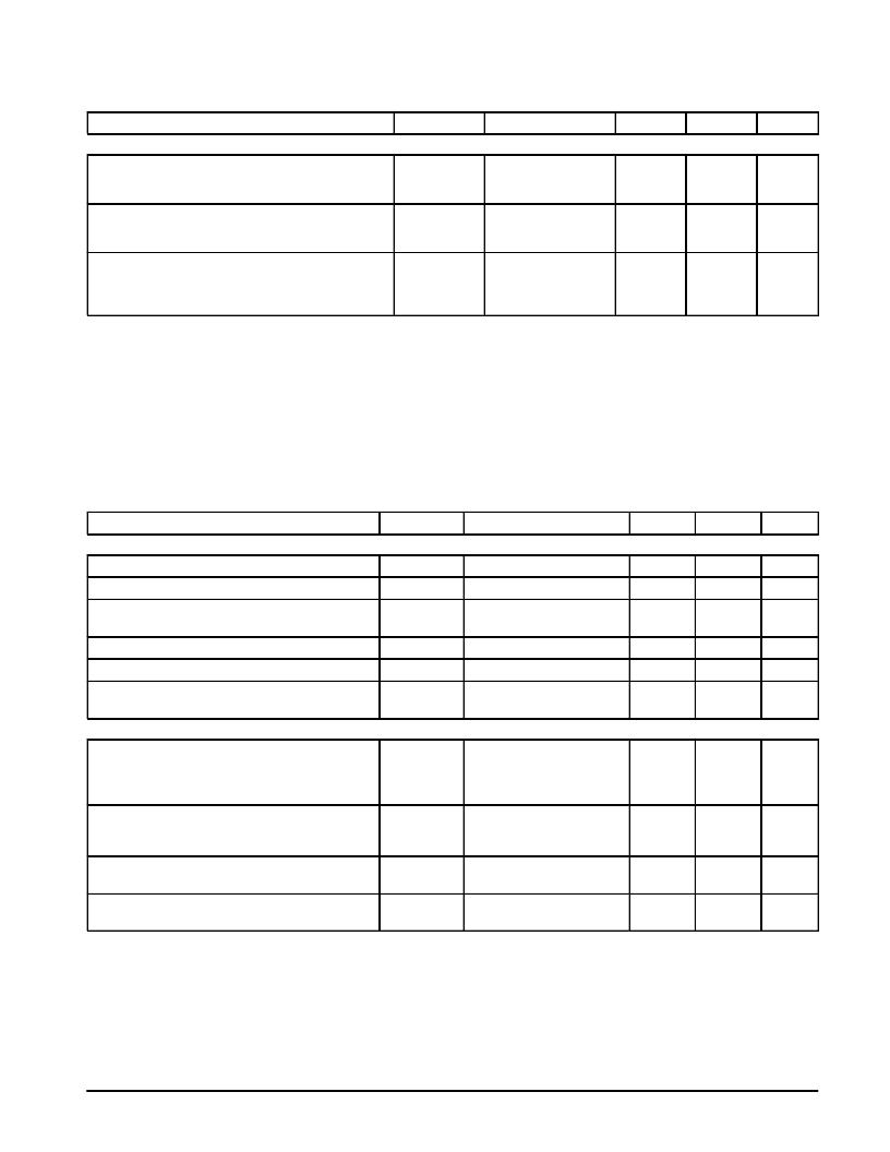
DC ELECTRICAL CHARACTERISTICS
(continued)
(TA = 25
°
C, VCC = 5.0 V
±
5%. Unless otherwise noted, minimum and maximum
limits apply over the recommended ambient operating temperature and power supply voltage ranges for each MC68160, B, C except where
noted.)
Characteristic
Symbol
Test Conditions
Min
Max
Unit
TWISTED PAIR TRANSMITTER OUTPUTS
Differential Output Voltage
IDLE Mode
Open Circuit
VODFTPI
VODFTPO
Note 6
Note 8
–
–
±
50
5.25
mV
V
Differential Output Impedance
TRANSMISSION Mode
IDLE Mode
RODFTPT
RODFTPI
Note 8
12
8.0
28
29
Common Mode Output Impedance
TRANSMISSION Mode (MC68160, MC68160C)
TRANSMISSION Mode (MC68160B)
IDLE Mode
ROCMTPT
ROCMTPT
ROCMTPI
Note 8
3.0
2.5
1.0
7.0
7.0
10
k
NOTES:
1. APORT, TPAPCE, CS0, CS1, CS2, TX, LOOP, TPFULDL, TPSQEL and TPEN (In Input Mode).
2. TCLK, RX, RCLK, RENA and CLSN.
3. TPPLR, TPLIL, TPJABB, TXLED, RXLED, CLLED and TPEN (In Output Mode).
4. TPPLR, TPLIL, CLLED, TXLED and RXLED.
5. TPJABB and TPEN (In Output Mode).
6. Measured with Test Load B1 (shown in Figure 3), applied directly to the TPTX+/– pins of the device.
7. Measured differentially with Test Load B2 (shown in Figure 4), applied directly to the TPTX+/– pins of the device.
8. Measured directly on the TPTX+/– pins of the device.
9. Measured with Test Load B3 (shown in Figure 5), applied directly to the TPRX+/– pins of the device.
10. The Common Mode Input Voltage is between 1.8 V and 3.2 V.
DC ELECTRICAL CHARACTERISTICS
(Unless otherwise noted, minimum and maximum limits apply over the recommended
ambient operating temperature and power supply voltage ranges for each MC68160, B, C except where noted.)
Characteristic
Symbol
Test Conditions
Min
Max
Unit
AUI RECEIVER INPUTS
Input Voltage Range (DC + AC)
VIA
VIDFA
VIASQ
–
1.0
4.2
V
Differential Mode Input Voltage Range
–
±
318
±
1315
mV
Differential Input Squelch Threshold Voltage
(MC68160, MC68160C)
–
–275
–175
mV
Differential Mode Input Voltage Range (MC68160B)
VIASQ
RICMA
RIDFA
–
–300
–175
mV
Common Mode Input Resistance
1.0 V < VICMA < 4.2 V
1.0 V < VICMA < 4.2 V
318 mV < VIDMA < 1315 mV
1.5
–
k
Differential Input Resistance (ARX, ACX Inputs)
5.0
–
k
AUI TRANSMITTER OUTPUTS
Common Mode Output Voltage
IDLE Mode
ACTIVE Mode
STANDBY Mode
VOCMIA
VOCMAA
VOCMSA
Figure 6
IO = –100
μ
A
Figure 6
1.0
1.0
VDD – 2.0
4.2
4.2
VDD – 1.2
V
Differential Output Voltage
IDLE Mode
ACTIVE Mode
VODFIA
VODFAA
–
±
600
±
40
±
1315
mV
Differential Output Load Current
IDLE Mode
IODFIA
Figure 7
–
±
4.0
mA
Output Short Circuit Current
IODSA
Output Short Circuited to
VDD or GND
–
±
150
mA
相關(guān)PDF資料 |
PDF描述 |
|---|---|
| MC68160 | ENHANCED ETHERNET INTERFACE TRANSCEIVER |
| MC68160B | ENHANCED ETHERNET INTERFACE TRANSCEIVER |
| MC68160C | ENHANCED ETHERNET INTERFACE TRANSCEIVER |
| MC68160CFB | 3.0V 100ppm/Degrees C, 50uA in SOT23-3 Series (Bandgap) Voltage Reference 3-SOT-23 -40 to 125 |
| MC68160FB | ENHANCED ETHERNET INTERFACE TRANSCEIVER |
相關(guān)代理商/技術(shù)參數(shù) |
參數(shù)描述 |
|---|---|
| MC68160C | 制造商:MOTOROLA 制造商全稱:Motorola, Inc 功能描述:ENHANCED ETHERNET INTERFACE TRANSCEIVER |
| MC68160CFB | 制造商:MOTOROLA 制造商全稱:Motorola, Inc 功能描述:ENHANCED ETHERNET INTERFACE TRANSCEIVER |
| MC68160FB | 制造商:Freescale Semiconductor 功能描述: 制造商:Motorola Inc 功能描述: 制造商: 功能描述: 制造商:undefined 功能描述: |
| MC68181 | 制造商:FREESCALE 制造商全稱:Freescale Semiconductor, Inc 功能描述:Advance Information ROAMING FLEX chip SIGNAL PROCESSOR |
| MC68184 | 制造商:MOTOROLA 制造商全稱:Motorola, Inc 功能描述:Broadband Interface Controller |
發(fā)布緊急采購,3分鐘左右您將得到回復(fù)。