- 您現(xiàn)在的位置:買(mǎi)賣(mài)IC網(wǎng) > PDF目錄69030 > MC8DE16G5APP-0XA FLASH MEMORY DRIVE CONTROLLER, PQFP PDF資料下載
參數(shù)資料
| 型號(hào): | MC8DE16G5APP-0XA |
| 元件分類(lèi): | 存儲(chǔ)控制器/管理單元 |
| 英文描述: | FLASH MEMORY DRIVE CONTROLLER, PQFP |
| 封裝: | LQFP |
| 文件頁(yè)數(shù): | 4/62頁(yè) |
| 文件大小: | 740K |
| 代理商: | MC8DE16G5APP-0XA |
第1頁(yè)第2頁(yè)第3頁(yè)當(dāng)前第4頁(yè)第5頁(yè)第6頁(yè)第7頁(yè)第8頁(yè)第9頁(yè)第10頁(yè)第11頁(yè)第12頁(yè)第13頁(yè)第14頁(yè)第15頁(yè)第16頁(yè)第17頁(yè)第18頁(yè)第19頁(yè)第20頁(yè)第21頁(yè)第22頁(yè)第23頁(yè)第24頁(yè)第25頁(yè)第26頁(yè)第27頁(yè)第28頁(yè)第29頁(yè)第30頁(yè)第31頁(yè)第32頁(yè)第33頁(yè)第34頁(yè)第35頁(yè)第36頁(yè)第37頁(yè)第38頁(yè)第39頁(yè)第40頁(yè)第41頁(yè)第42頁(yè)第43頁(yè)第44頁(yè)第45頁(yè)第46頁(yè)第47頁(yè)第48頁(yè)第49頁(yè)第50頁(yè)第51頁(yè)第52頁(yè)第53頁(yè)第54頁(yè)第55頁(yè)第56頁(yè)第57頁(yè)第58頁(yè)第59頁(yè)第60頁(yè)第61頁(yè)第62頁(yè)

NAND Flash-based Solid State Disk
12
Nov. 15. 2006
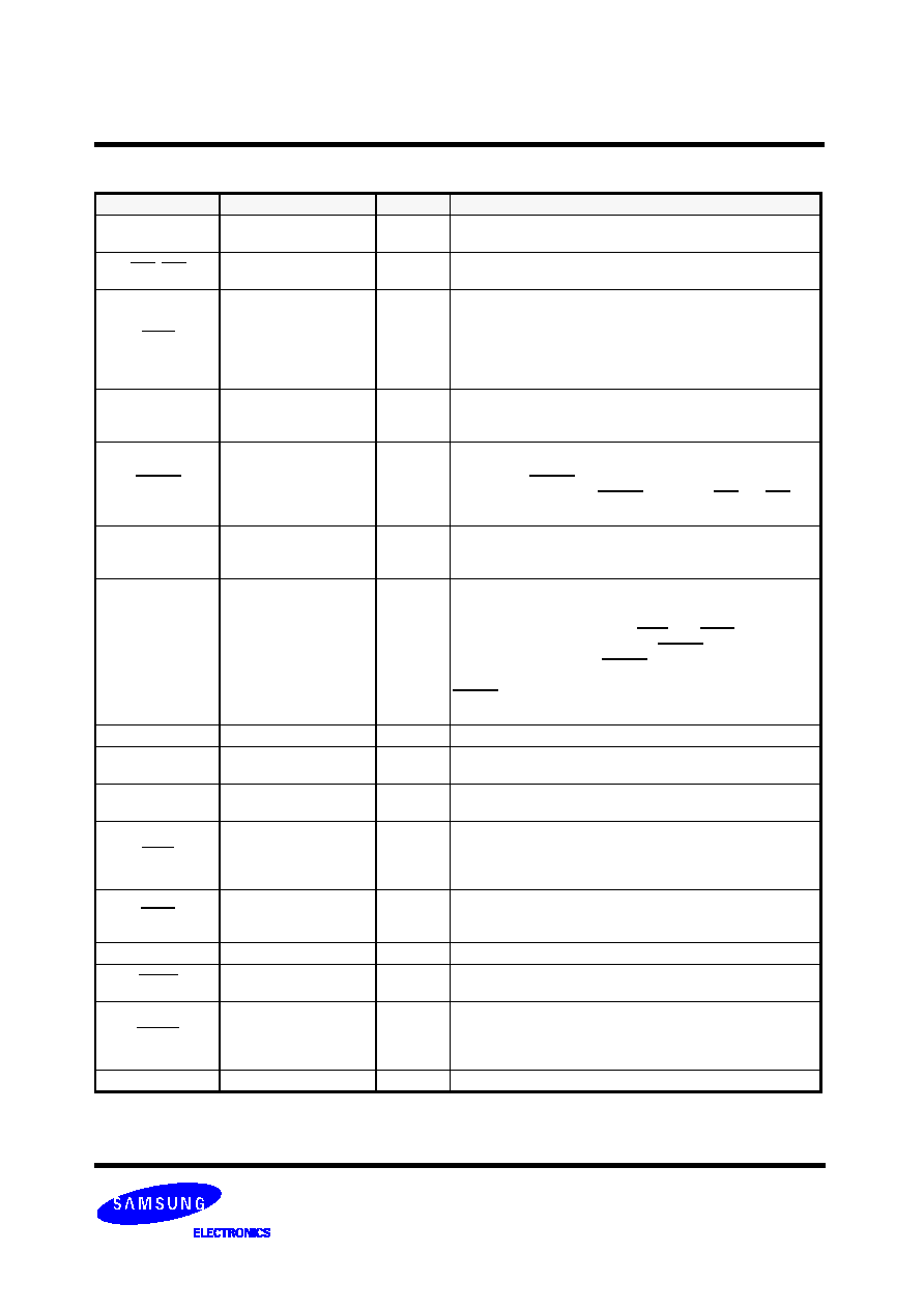
Signal name
Pin NO
Type
Description
A2 - A0
36,33,35
I
ADDRESS INPUTS: The Address signal are asserted by the host
to access the task register in the device.
CS0, CS1
37,38
I
CHIP SELECTS: These are the chip select signals used to select
the control block registers.
CSEL
28
I
CABLE SELECT: This internally pulled up signal is used to config-
ure this device as a Master or a Slave when the jumper configura-
tion is in CSEL mode.
When this pin is grounded by the host, this device is configured as
a Master. When this pin is open, this device is configured as a
slave.
D15 - D0
18,16,14,12,10,8,6,4,3,5,7,
9,11,13,15,17
I/O
DATA INPUTS/OUTPUTS: This is 8 or 16 bit bi-directional inter-
face between the host and device. The lower 8 bits are used for 8
bit register transfers.
DMACK
29
I
DMA ACKNOWLEDGE: This signal is used by the host in
response to DMARQ to initiate DMA transfers.
The DMARQ/DMACK handshake is used to provide flow control
during the transfer. When DMACK is asserted, CS0 ans CS1 shall
not be asserted and transfers shall be 16bits wide.
DASP
39
I/O
DISK ACTIVE/SLAVE PRESENT: This open drain output signal is
asserted low any time the drive is active. In a master/slave to
inform the master a slave is present.
DMARQ
21
O
DMA REQUEST: This signal is used for DMA transfers between
the host and device. DMARQ shall be asserted by the device when
the device is ready to transfer data to/from the host. The direction
of data transfer is controller by IORD and IOWR. This signal is
used in a handshake manner with DMACK, i.e the device shall
wait until the host asserts DMACK before negating DMARQ, and
re-assert DMARQ if there is more data to transfer. The DMARQ/
DMACK handshake is used to provide flow control during the
transfer.
GND
2,19,22,24,26,30,40,43
-
GROUND: Device Ground.
INTRQ
31
O
INTERRUPT REQUEST: This signal is an active high interrupt
request to the host.
IORDY
27
I
I/O CHANNEL READY: The signal is negated to extend the host
transfer cycle of any host register access.
IORD
25
I
DEVICE I/O READ: This is the read strobe signal from the host.
The falling edge of IORD enables data from the device onto the
data bus. The rising edge of IORD latches data at the host. The
host shall not act on the data until it is latched.
IOWR
23
I
DEVICE I/O WRITE: This is the write strobe signal from the host.
The rising edge of IOWR# latches data from the data bit signals.
The device will not act on the data until it is latched.
KEY
20
-
KEY: Peserved for the Connector Key.
PDIAG
34
I/O
PASS DIAGNOSTIC: This open drain signal is asserted by the
Slave to indicate to the Master that it has passed its diagnostics.
RESET
1I
DEVICE RESET: Active Low. When Active, this sets all internal
registers to their default state. This signal shall be held asserted
until at least 25us after power has been stabilized during the
device power on.
VCC
41,42
-
DEVICE POWER SUPPLY: Device Power 3.3/5V
4.4 Signal Descriptions
相關(guān)PDF資料 |
PDF描述 |
|---|---|
| MCAQE32G8APP-0XA | FLASH MEMORY DRIVE CONTROLLER, PQFP |
| MC908AZ32AVFU | 8-BIT, FLASH, 8.4 MHz, MICROCONTROLLER, PQFP64 |
| MC908AZ32ACFU | 8-BIT, FLASH, 8.4 MHz, MICROCONTROLLER, PQFP64 |
| MC908AZ32AMFU | 8-BIT, FLASH, 8.4 MHz, MICROCONTROLLER, PQFP64 |
| MC908AZ32AMFUE | 8-BIT, FLASH, 8.4 MHz, MICROCONTROLLER, PQFP64 |
相關(guān)代理商/技術(shù)參數(shù) |
參數(shù)描述 |
|---|---|
| MC8DE16G5APP-0XA00 | 制造商:Samsung Semiconductor 功能描述: |
| MC8F-1 | 制造商:SPC Multicomp 功能描述:TRANSFORMER VARIABLE 8A |
| MC8F-1 | 制造商:SPC Multicomp 功能描述:TRANSFORMER VARIABLE 8A |
| MC8M | 制造商:G & J HALL 功能描述:STEP DRILL MULTICUT 14-24MM X 2MM |
| MC8MD9P1B10M2RES | 制造商:SPC Multicomp 功能描述:SWITCH DPST OFF-MOM PCB 制造商:SPC Multicomp 功能描述:SWITCH, DPST, OFF-MOM, PCB 制造商:SPC Multicomp 功能描述:SWITCH, DPST, OFF-MOM, PCB; Contact Configuration:DPST; Switch Operation:Off-(On); Contact Voltage AC Nom:20V; IP Rating:(Not Available); Contact Voltage DC Nom:20V; Contact Current Max:400mA; Actuator Style:Round; Switch ;RoHS Compliant: Yes |
發(fā)布緊急采購(gòu),3分鐘左右您將得到回復(fù)。