- 您現(xiàn)在的位置:買賣IC網 > PDF目錄10416 > MCP2022P-500E/SL (Microchip Technology)IC TXRX LIN ON-BOARD VREG 14SOIC PDF資料下載
參數資料
| 型號: | MCP2022P-500E/SL |
| 廠商: | Microchip Technology |
| 文件頁數: | 49/52頁 |
| 文件大?。?/td> | 0K |
| 描述: | IC TXRX LIN ON-BOARD VREG 14SOIC |
| 產品培訓模塊: | Microchip MCP20xx LIN Transceiver Overview |
| 標準包裝: | 57 |
| 系列: | * |
第1頁第2頁第3頁第4頁第5頁第6頁第7頁第8頁第9頁第10頁第11頁第12頁第13頁第14頁第15頁第16頁第17頁第18頁第19頁第20頁第21頁第22頁第23頁第24頁第25頁第26頁第27頁第28頁第29頁第30頁第31頁第32頁第33頁第34頁第35頁第36頁第37頁第38頁第39頁第40頁第41頁第42頁第43頁第44頁第45頁第46頁第47頁第48頁當前第49頁第50頁第51頁第52頁
MCP2021/2/1P/2P
DS22018F-page 6
2005-2012 Microchip Technology Inc.
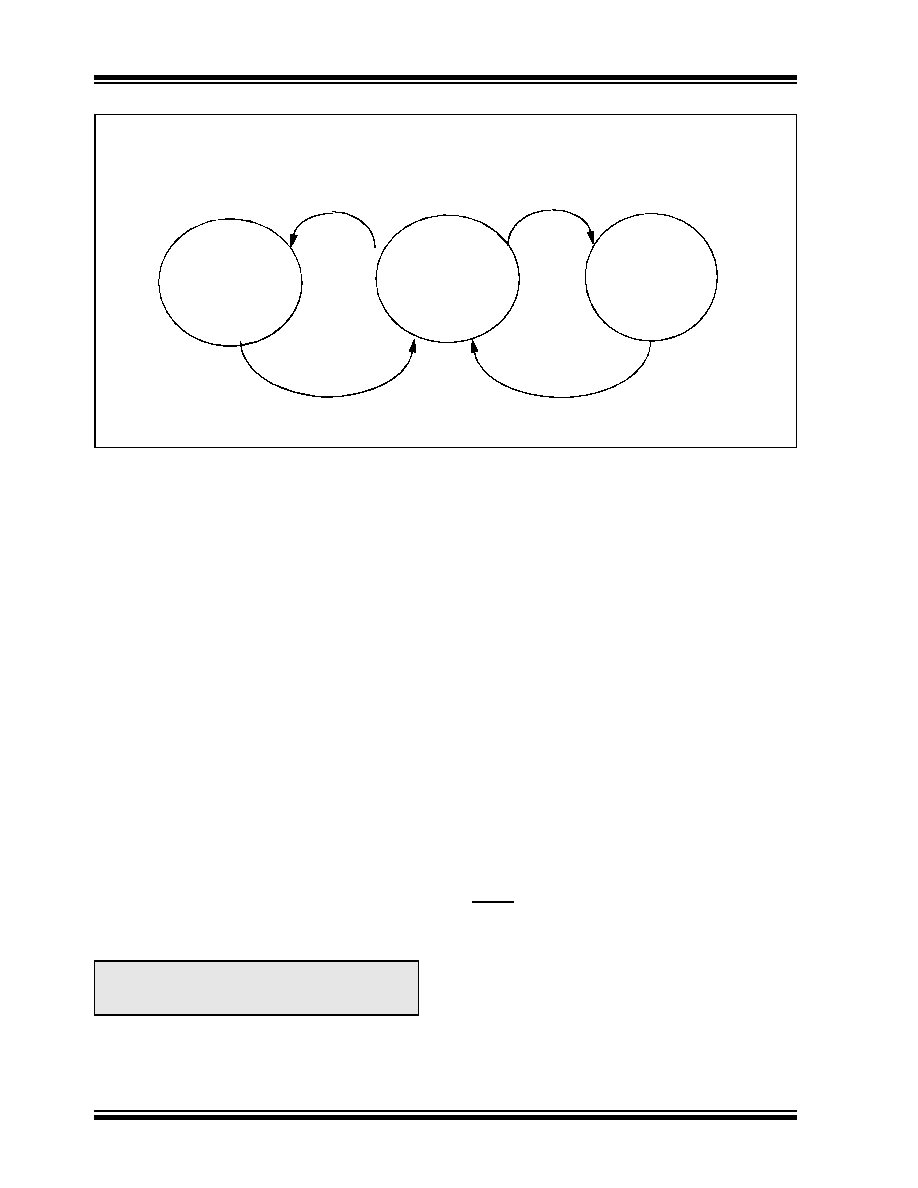
FIGURE 1-1:
Thermal Shutdown State Diagrams.
1.3
Modes of Operation
For an overview of all operational modes, please refer
to Table 1-1.
1.3.1
POWER-ON RESET MODE
Upon application of VBB, the device enters Power-on
Reset mode (POR). During this mode, the part main-
tains the digital section in a Reset mode and waits until
the voltage on pin VBB rises above the “ON” threshold
(Typ. 5.75V) to enter to the Ready mode. If during the
operation, the voltage on pin VBB falls below the “OFF”
threshold (Typ. 4.25V), the part comes back to the POR
mode.
1.3.2
POWER-DOWN MODE
In the Power-Down mode, the transmitter and the
voltage regulator are off. Only the receiver wake-up
from LIN bus section, and the CS/LWAKE pin wake-up
circuits are in operation. This is the lowest power mode.
If pin CS/LWAKE goes to a high level during Power-
Down mode, the device immediately enters Ready
mode and enables the voltage regulator; and after the
output has stabilized (approximately 0.3 ms to 1.2 ms),
the device goes to Operation mode or Transmitter-Off
mode (see Figure 1-2 for MCP2021/2 and Figure 1-3
for MCP2021P/2P).
LIN bus activity will also change the device from
Power-Down mode to Ready mode. MCP2021/2
wakes up on dominant level of LIN bus, and
MCP2021P/2P on a falling edge that follows a domi-
nant level lasting 20 s of time.
The Power-Down mode can be reached through either
Operation mode or Transmitter-Off mode.
1.3.3
READY MODE
Upon entering Ready mode, the voltage regulator and
receiver-threshold-detect circuit are powered up. The
transmitter remains in off state. The device is ready to
receive data as soon as the regulator is stabilized, but
not to transmit. If a microcontroller is being driven by
the voltage regulator output, it will go through a POR
and initialization sequence. The LIN pin is in the reces-
sive state for MCP2021/2 and in floating state for
MCP2021P/2P.
The device will stay in Ready mode until the output of
the voltage regulator has stabilized and the CS/LWAKE
pin is true (‘1’). After VREG is stable and CS/LWAKE is
high, MCP2021/2 will enter Operation mode; and
MCP2021P/2P will enter either Operation mode or
Transmitter-Off mode, depending on the level of the
FAULT/TXE pin (refer to Figure 1-3).
1.3.4
OPERATION MODE
In this mode, all internal modules are operational.
The device will go into the Power-Down mode on the
falling edge of CS/LWAKE.
For the MCP2021P/2P devices, the pull-up resistor is
switched on only in this mode.
Operation
Mode
Transmitter
Shutdown
LIN Bus
Voltage
Shutdown
Regulator
Output
Temperature <SHUTDOWNTEMP
Overload
to VBB
Overload
Temperature <SHUTDOWNTEMP
Note:
The above time interval <1.2 ms assumes
12V VBB input and no thermal shutdown
event.
相關PDF資料 |
PDF描述 |
|---|---|
| MCP2022P-330E/SL | IC TXRX LIN ON-BOARD VREG 14SOIC |
| VE-J6R-MX | CONVERTER MOD DC/DC 7.5V 75W |
| VE-J6M-MX | CONVERTER MOD DC/DC 10V 75W |
| VE-J6H-MX | CONVERTER MOD DC/DC 52V 75W |
| VE-J6F-MX | CONVERTER MOD DC/DC 72V 75W |
相關代理商/技術參數 |
參數描述 |
|---|---|
| MCP2022PT | 制造商:MICROCHIP 制造商全稱:Microchip Technology 功能描述:LIN Transceiver with Voltage Regulator |
| MCP2022PT-330E/SL | 功能描述:LIN 收發(fā)器 LIN Transceiver with Vreg and LIN RoHS:否 制造商:NXP Semiconductors 工作電源電壓: 電源電流: 最大工作溫度: 封裝 / 箱體:SO-8 |
| MCP2022PT-330E/ST | 功能描述:LIN 收發(fā)器 LIN Transceiver with Vreg and LIN RoHS:否 制造商:NXP Semiconductors 工作電源電壓: 電源電流: 最大工作溫度: 封裝 / 箱體:SO-8 |
| MCP2022PT-500E/SL | 功能描述:LIN 收發(fā)器 LIN Transceiver with Vreg and LIN RoHS:否 制造商:NXP Semiconductors 工作電源電壓: 電源電流: 最大工作溫度: 封裝 / 箱體:SO-8 |
| MCP2022PT-500E/ST | 功能描述:LIN 收發(fā)器 LIN Transceiver with Vreg and LIN RoHS:否 制造商:NXP Semiconductors 工作電源電壓: 電源電流: 最大工作溫度: 封裝 / 箱體:SO-8 |
發(fā)布緊急采購,3分鐘左右您將得到回復。