- 您現(xiàn)在的位置:買賣IC網(wǎng) > PDF目錄11718 > MCZ33989EG (Freescale Semiconductor)IC SYSTEM BASIS CHIP CAN 28-SOIC PDF資料下載
參數(shù)資料
| 型號: | MCZ33989EG |
| 廠商: | Freescale Semiconductor |
| 文件頁數(shù): | 18/72頁 |
| 文件大?。?/td> | 0K |
| 描述: | IC SYSTEM BASIS CHIP CAN 28-SOIC |
| 標(biāo)準(zhǔn)包裝: | 26 |
| 系列: | * |
| 應(yīng)用: | * |
| 接口: | * |
| 電源電壓: | * |
| 封裝/外殼: | 28-SOIC(0.295",7.50mm 寬) |
| 供應(yīng)商設(shè)備封裝: | 28-SOIC W |
| 包裝: | 管件 |
| 安裝類型: | 表面貼裝 |
第1頁第2頁第3頁第4頁第5頁第6頁第7頁第8頁第9頁第10頁第11頁第12頁第13頁第14頁第15頁第16頁第17頁當(dāng)前第18頁第19頁第20頁第21頁第22頁第23頁第24頁第25頁第26頁第27頁第28頁第29頁第30頁第31頁第32頁第33頁第34頁第35頁第36頁第37頁第38頁第39頁第40頁第41頁第42頁第43頁第44頁第45頁第46頁第47頁第48頁第49頁第50頁第51頁第52頁第53頁第54頁第55頁第56頁第57頁第58頁第59頁第60頁第61頁第62頁第63頁第64頁第65頁第66頁第67頁第68頁第69頁第70頁第71頁第72頁
Analog Integrated Circuit Device Data
Freescale Semiconductor
25
33989
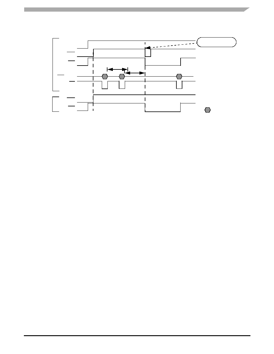
FUNCTIONAL DEVICE OPERATION
RESET AND WATCHDOG PINS, SOFTWARE WATCHDOG OPERATIONS
Figure 10. Reset and Watchdog Functions Diagram in Modes 1 and 2
WAKE-UP CAPABILITIES
Several wake-up capabilities are available for the device when it is in Sleep, or Stop modes. When a wake-up has occurred,
the wake-up event is stored into the WUR or CAN registers. The MCU can then access to the wake-up source. The wake-up
options are able to be selected through the SPI while the device is in Normal or Standby mode and prior to entering low power
mode (Sleep or Stop mode). When a wake-up occurs from sleep mode the device activates VDD1. It generates an interrupt if
wake-up occurs from Stop mode.
WAKE-UP FROM WAKE-UP INPUTS (L0:L3) WITHOUT CYCLIC SENSE
The wake-up lines are dedicated to sense external switch states and if changes occur to wake-up the MCU (in Sleep or Stop
modes). The wake-up pins are able to handle 40 V DC. The internal threshold is 3.0 V typical and these inputs can be used as
an input port expander. The wake-up inputs state are read through SPI (register WUR).
In order to select and activate direct wake-up from the LX inputs, the WUR register must be configured with the appropriate
level sensitivity. Additionally, the LPC register must be configured with 0x0 data (bits LX2HS1and HS1AUTO are set at 0).
Level sensitivity is selected by WUR register. Level sensitivity is configured by a pair of Lx inputs: L0 and L1 level sensitivity
are configured together while L2 and L3 are configured together.
CYCLIC SENSE WAKE-UP (CYCLIC SENSE TIMER AND WAKE-UP INPUTS L0, L1, L2, L3)
The SBC can wake-up upon state change of one of the four wake-up input lines (L0, L1, L2 and L3) while the external pull-up
or pull down resistor of the switches associated to the wake-up input lines are biased with HS1 VSUP switch. The HS1 switch is
activated in Sleep or Stop modes from an internal timer. Cyclic Sense and Forced Wake-up are exclusive. If Cyclic Sense is
enabled the forced wake-up can not be enabled.
In order to select and activate the cyclic sense wake-up from the Lx inputs the WUR register must be configured with the
appropriate level sensitivity, and the LPC register must be configured with 1xx1 data (bit LX2HS1 set at 1 and bit HS1AUTO set
at 1). The wake-up mode selection (direct or cyclic sense) is valid for all 4 wake-up inputs.
FORCED WAKE-UP
The SBC can wake-up automatically after a predetermined time spent in Sleep or Stop mode. Cyclic sense and Forced wake-
up are exclusive. If Forced wake-up is enabled (FWU bit set to 1 in LPC register) the Cyclic Sense can not be enabled.
CAN INTERFACE WAKE-UP
The device incorporates a high-speed 1MBaud CAN physical interface. Its electrical parameters for the CANL, CANH, RX and
TX pins are compatible with ISO 11898 specification (IS0 11898: 1993(E)). The control of the CAN physical interface operation
is accomplished through the SPI. CAN modes are independent of the SBC operation modes.
The device can wake-up from a CAN message if the CAN wake-up is enabled. Please refer to the CAN module description
for detail of wake-up detection.
RST
WD
VDD1
SPI
SPI CS
Watchdog Timeout
Watchdog
Period
WD Clear
MODE 1
RST
MODE 2
Register
Addressed
WD
相關(guān)PDF資料 |
PDF描述 |
|---|---|
| V150A12E500B3 | CONVERTER MOD DC/DC 12V 500W |
| MCZ33884EGR2 | IC MULTIPLE CONTACT MON 24-SOIC |
| V110B8H150BL3 | CONVERTER MOD DC/DC 8V 150W |
| MS27484T18A35SN | CONN PLUG 66POS STRAIGHT W/SCKT |
| MCZ33990EFR2 | IC TRANSCEIVER J-1850 BUS 8-SOIC |
相關(guān)代理商/技術(shù)參數(shù) |
參數(shù)描述 |
|---|---|
| MCZ33989EG | 制造商:Freescale Semiconductor 功能描述:IC SYSTEM BASIS W/CAN TRANCEIVER |
| MCZ33989EGR2 | 功能描述:網(wǎng)絡(luò)控制器與處理器 IC SBC-HS RoHS:否 制造商:Micrel 產(chǎn)品:Controller Area Network (CAN) 收發(fā)器數(shù)量: 數(shù)據(jù)速率: 電源電流(最大值):595 mA 最大工作溫度:+ 85 C 安裝風(fēng)格:SMD/SMT 封裝 / 箱體:PBGA-400 封裝:Tray |
| MCZ33990EF | 功能描述:網(wǎng)絡(luò)控制器與處理器 IC CLASS B SERIAL TRANS. RoHS:否 制造商:Micrel 產(chǎn)品:Controller Area Network (CAN) 收發(fā)器數(shù)量: 數(shù)據(jù)速率: 電源電流(最大值):595 mA 最大工作溫度:+ 85 C 安裝風(fēng)格:SMD/SMT 封裝 / 箱體:PBGA-400 封裝:Tray |
| MCZ33990EF | 制造商:Freescale Semiconductor 功能描述:TRANCEIVER J-1850 CLASS B 8SOIC |
| MCZ33990EF/R2 | 制造商:FREESCALE 制造商全稱:Freescale Semiconductor, Inc 功能描述:Enhanced Class B Serial Transceiver |
發(fā)布緊急采購,3分鐘左右您將得到回復(fù)。